Cover assembly for an in-floor fitting

a technology for coverings and fittings, applied in the direction of electrical apparatus casings/cabinets/drawers, coupling device connections, casings/cabinets/drawers, etc., can solve the problem of fittings being exposed to water

Inactive Publication Date: 2006-08-01
THE WIREMOLD CO
View PDF58 Cites 28 Cited by
  • Summary
  • Abstract
  • Description
  • Claims
  • Application Information

AI Technical Summary

Benefits of technology

[0005]A cover assembly is usable with a fitting of which is disposed in a floor and has an inner compartment accessible through an opening in the upper surface of the floor. The fitting is configured so that source cables can be routed into the inner compartment from a location below the upper surface of the floor. The cover assembly includes a first portion which overlies the floor opening and is connectable to the fitting. The first portion may be in the form of a trim flange. The first portion includes a central opening which overlies the floor opening to provide access to receptacles carried by the fitting. The first portion may function as a mounting bracket for supporting receptacles, such as power receptacles and / or a communications / data receptacles. Alternatively, some or all of the receptacles may be supported by mounting brackets within the fitting itself. The cover assembly also includes a second portion which is mounted on the first portion and which overlies the receptacles carried by the fitting. The second portion includes access doors movable between closed positions to prevent access to the receptacles and open positions at which the receptacles are exposed and accessible from above.

Problems solved by technology

As a result, such fittings may be exposed to water, e.g. during carpet cleaning.

Method used


Image

  • Cover assembly for an in-floor fitting
  • Cover assembly for an in-floor fitting
  • Cover assembly for an in-floor fitting

Examples


Embodiment Construction

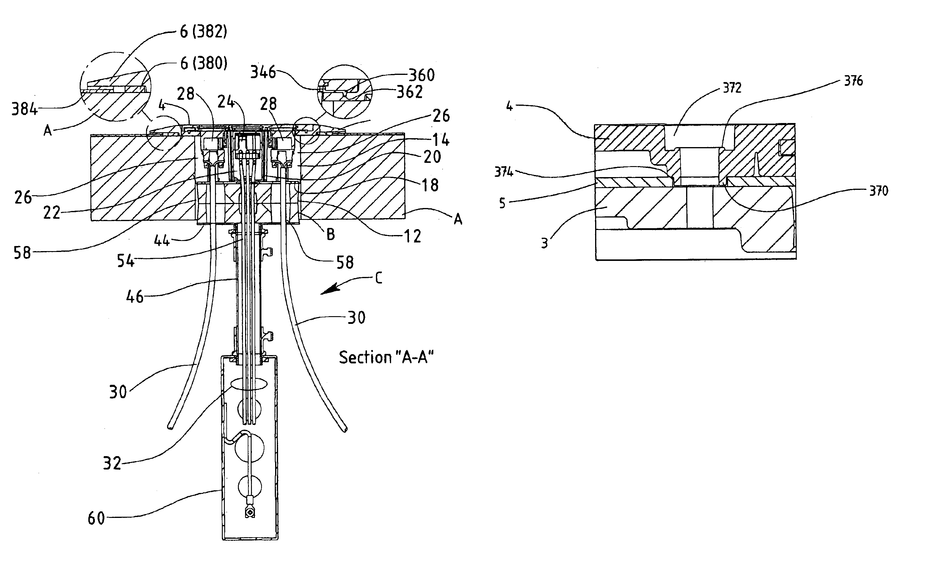
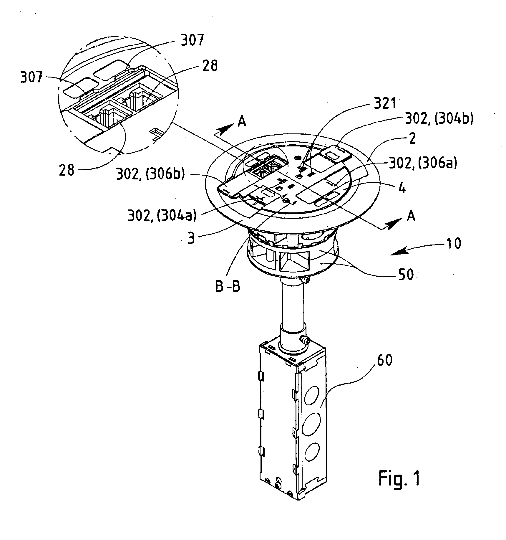
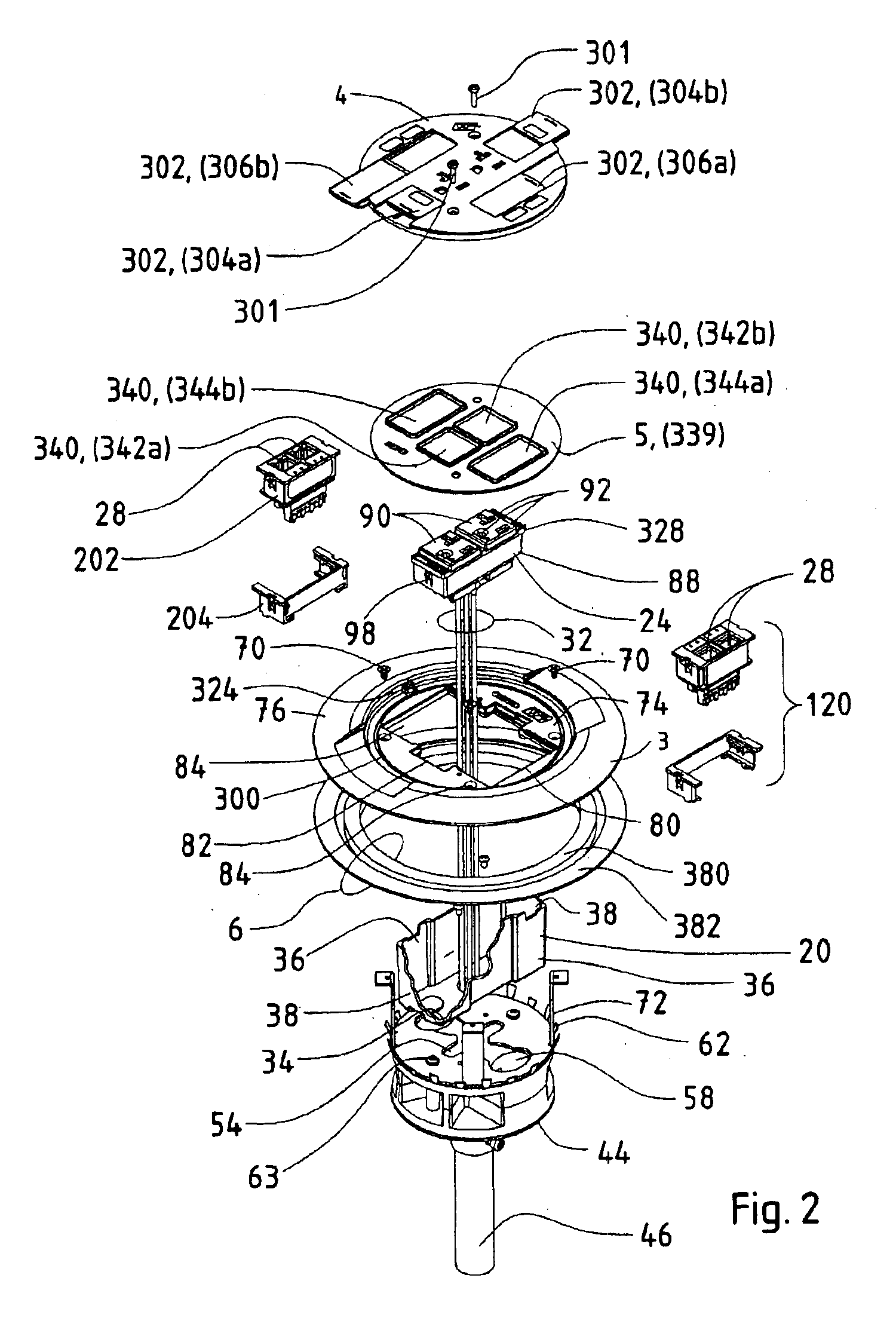
[0027]Referring to FIGS. 1-3, a water-tight cover assembly 2 for an in-floor fitting 10 generally includes a first portion in the form of a trim flange 3, a second portion in the form of a slide holder or cover plate 4, a first or internal seal member 5, and a second or external seal member 6. In the illustrated embodiment, the cover assembly 2 is described in connection with a poke-thru fitting. It will be appreciated, however, that the cover assembly 2 could readily be adapted for use with other types of in-floor fittings, such as preset or afterset fittings as are used with in-floor raceway systems.

[0028]The poke-thru fitting 10 may be constructed generally in accordance with the poke-thru fittings disclosed in U.S. Pat. No. 6,175,078, which issued Jan. 16, 2001 and is entitled “Flush Poke-thru Wiring Fitting Having A Height Adjustable Data Jack Mounting Bracket” (the “'078 patent”) and U.S. patent application Ser. No. 09 / 642,951, which was filed on Aug. 21, 2000 and is entitled ...


PUM


Abstract

A cover assembly is provided for preventing water infiltration into an in-floor receptacle fitting, such as a poke-thru fitting. The cover assembly includes a trim flange which overlies the fitting and is adapted to support at least one receptacle within the fitting. A cover plate is mounted on the trim flange includes access doors for selectively covering and exposing the receptacles. A first seal member is interposed between the cover plate and the trim flange for sealing against water infiltration therebetween. The first seal may be in the form of a planar gasket or O-ring. A second seal, in the form of at least one compressible gasket, extends around the perimeter of the floor opening and is adapted to be compressed between the trim flange and the surface of the floor. The cover plate may also include top and bottom portions and a third seal member interposed between the top and bottom portions.

Description

RELATED APPLICATIONS[0001]This application claims priority of Provisional Application Ser. No. 60 / 311,013, filed Aug. 8, 2001 and Provisional Application Ser. No. 60 / 263,483, filed Jan. 23, 2001, and is a continuation-in-part of application serial number U.S. patent application Ser. No. 09 / 978,731, filed Oct. 15, 2001, now U.S. Pat No. 6,612,081.FEDERALLY SPONSORED RESEARCH OR DEVELOPMENT[0002]Not ApplicableMICROFICHE / COPYRIGHT REFERENCE[0003]Not ApplicableBACKGROUND OF THE INVENTION[0004]In-floor fittings such as poke-thru fittings, after sets fittings, and preset fittings are installed in concrete floors to provide electrical receptacles and communication / data receptacles (or jacks) at desired locations in buildings. As a result, such fittings may be exposed to water, e.g. during carpet cleaning. It is desirable that such fittings are designed to prevent moisture infiltration from above the floor. In this respect, Underwriters Laboratories (UL) is proposing certification standards...

Claims


Application Information

Patent Timeline
Patent Type & Authority Patents(United States)
IPC IPC(8): H05K5/03H02G3/18
CPCH02G3/185H02G3/14
Inventor COLE, MICHAEL T.BOWMAN, TIMENGLISH, STEPHEN T.KOHAUT, JOHNYOUNG, JOE
Owner THE WIREMOLD CO
Why Eureka
Try Eureka