Apparatus and method for controlling cold air circulation in refrigerator

a technology for refrigerators and apparatuses, applied in domestic cooling apparatus, refrigeration machines, refrigeration safety arrangements, etc., can solve the problems of deteriorating freshness of stored goods, unfavorable temperature control, etc., and achieve the effect of reducing temperature deviation

Inactive Publication Date: 2006-08-01
LG ELECTRONICS INC
View PDF19 Cites 33 Cited by
  • Summary
  • Abstract
  • Description
  • Claims
  • Application Information

AI Technical Summary

Benefits of technology

[0014]Therefore, the present invention is conceived to solve the aforementioned problems in the prior art. An object of the present invention is to minimize temperature deviation in a refrigerating chamber of a refrigerator.
[0015]Another object of the present invention is to precisely maintain the temperature of a vegetable storage chamber installed at a lower portion of the refrigerating chamber of the refrigerator.
[0016]A further object of the present invention is to minimize heat loss of cold air which is returned from the refrigerating chamber to an evaporator.

Problems solved by technology

However, there are the following problems in the conventional apparatus for controlling the cold air circulation constructed as such.
Consequently, freshness of the stored goods is deteriorated.
That is, according to the prior art, the cold air is not uniformly delivered to the entire refrigerating chamber 5.

Method used


Image

  • Apparatus and method for controlling cold air circulation in refrigerator
  • Apparatus and method for controlling cold air circulation in refrigerator
  • Apparatus and method for controlling cold air circulation in refrigerator

Examples


Embodiment Construction

[0031]Hereinafter, preferred embodiments of an apparatus and method for controlling cold air circulation in a refrigerator according to the present invention will be described in detail with reference to the accompanying drawings.

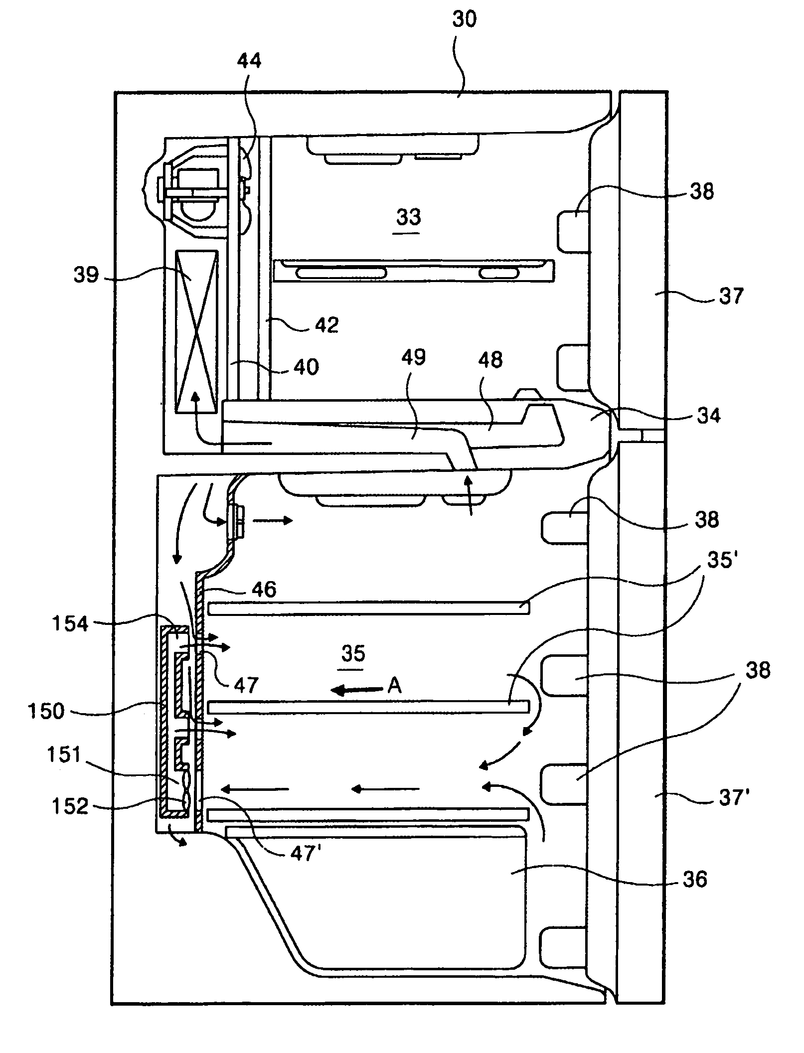
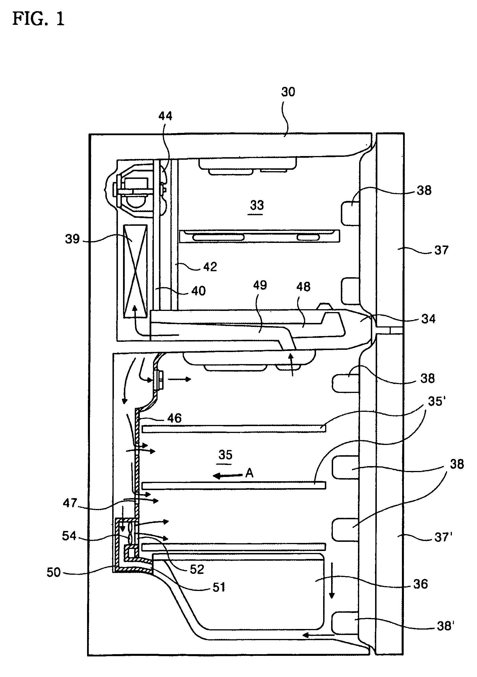
[0032]First, referring to FIGS. 1 and 2, one embodiment of the present invention will be described. As shown in these figures, the interior of a main body 30 of a refrigerator, which is comprised of walls having insulation layers, is provided with a freezing chamber 33 and a refrigerating chamber 35 as storage spaces. The freezing chamber 33 and the refrigerating chamber 35 are separated by a barrier 34 so that the freezing chamber 33 and the refrigerating chamber 35 are disposed at upper and lower portions of the main body, respectively.

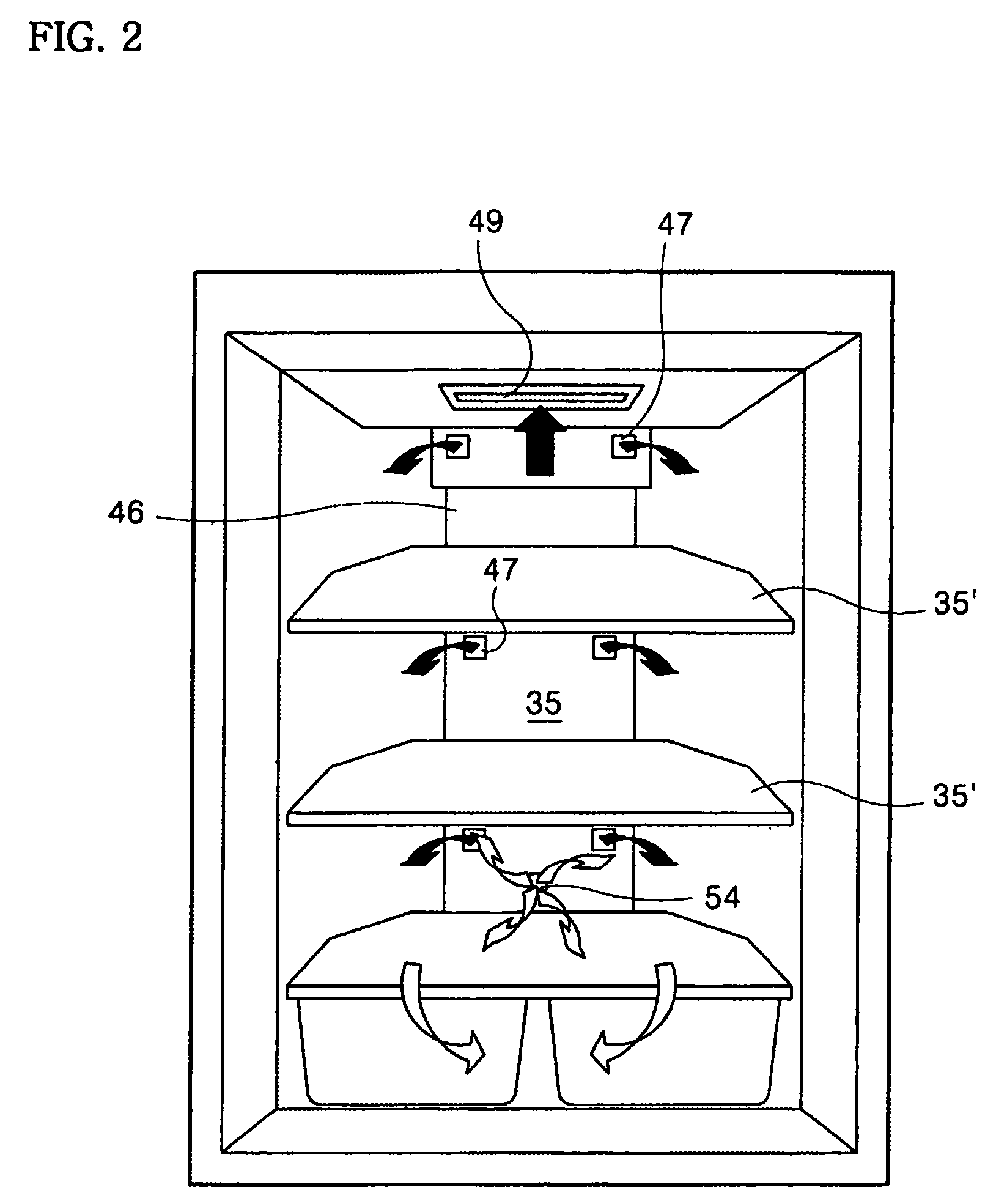
[0033]A plurality of shelves 35′ are installed in the refrigerating chamber 35 so that stored goods can be put thereon. A vegetable storage chamber 36 as an auxiliary storage space, which is separately formed by means of pa...


PUM


Abstract

The present invention relates to an apparatus and method for controlling cold air circulation in a refrigerator. The present invention re-circulates cold air, which has been discharged into a refrigerating chamber (35), so that the interior of the refrigerating chamber (35) can be maintained at a substantially uniform temperature and relatively low temperature cold air is prevented from being delivered to an evaporator (39). Particularly, the present invention further facilitates the cold air circulation at a lower portion of the refrigerating chamber (35) so that the temperature of the entire refrigerating chamber (35) can be kept to be uniform and the temperature of a vegetable storage chamber (36) can be set at a desired temperature. To this end, an embodiment of the present invention includes a circulation duct (50) configured to suck the cold air around the vegetable storage chamber (36) and to discharge it to a relatively upper portion of the refrigerating chamber (35). An inlet (51) of the circulation duct (50) is installed in vicinity of a reward lower portion of the vegetable storage chamber (36), and an outlet of the circulation duct (50) is open to above a shelf (35′) corresponding to a top end of the vegetable storage chamber (36). Further, a circulation fan (54) is installed at the outlet (52).

Description

BACKGROUND OF THE INVENTION[0001]1. Field of the Invention[0002]The present invention relates to a refrigerator, and more particularly, to an apparatus for controlling cold air circulation in a refrigerator, which allows the internal temperature throughout a refrigerating chamber of the refrigerator to be uniformly distributed.[0003]2. Description of the Prior Art[0004]FIG. 6 shows a sectional view of a refrigerator which employs a conventional apparatus for controlling cold air circulation therein. As shown in this figure, a freezing chamber 3 and a refrigerating chamber 5, which are-storage spaces formed in the interior of a main body 1 of the refrigerator, are separated from each other by a barrier 4. A plurality of shelves 5′ are installed at different levels in the refrigerating chamber 5 so that stored goods can be put on the shelves. A vegetable storage chamber 6 for separately storing fruits or vegetables therein is formed at a lowermost portion of the refrigerating chamber ...

Claims


Application Information

Patent Timeline
Patent Type & Authority Patents(United States)
IPC IPC(8): F25D17/04F25D17/06F25D17/08F25D29/00
CPCF25D17/065F25D29/00F25D2317/061F25D2700/12F25D2317/0672F25D2317/0682F25D2400/04F25D2317/067
Inventor SHIN, JUN-CHUL
Owner LG ELECTRONICS INC
Why Eureka
Try Eureka