Hydraulic overshot tool without a nozzle, and method of retrieving a cylinder

a technology of hydraulic overshot and nozzle, which is applied in the field of retrieving tools, can solve the problems of hydraulic release of overshot tools, and achieve the effect of high flow ra

Active Publication Date: 2006-08-01
WEATHERFORD TECH HLDG LLC
View PDF21 Cites 15 Cited by
  • Summary
  • Abstract
  • Description
  • Claims
  • Application Information

AI Technical Summary

Benefits of technology

[0023]The piston includes an upper shoulder surface and a lower shoulder surface. The upper shoulder surface is in pressure communication with the annular region around the tool. This is accomplished by fabricating a low-pressure port into the upper body portion. The lower shoulder surface is in pressure communication with the inner surface of the housing. Thus, the

Problems solved by technology

In the event retrieval is unsuccessful, the oversho

Method used


Image

  • Hydraulic overshot tool without a nozzle, and method of retrieving a cylinder
  • Hydraulic overshot tool without a nozzle, and method of retrieving a cylinder
  • Hydraulic overshot tool without a nozzle, and method of retrieving a cylinder

Examples


Embodiment Construction

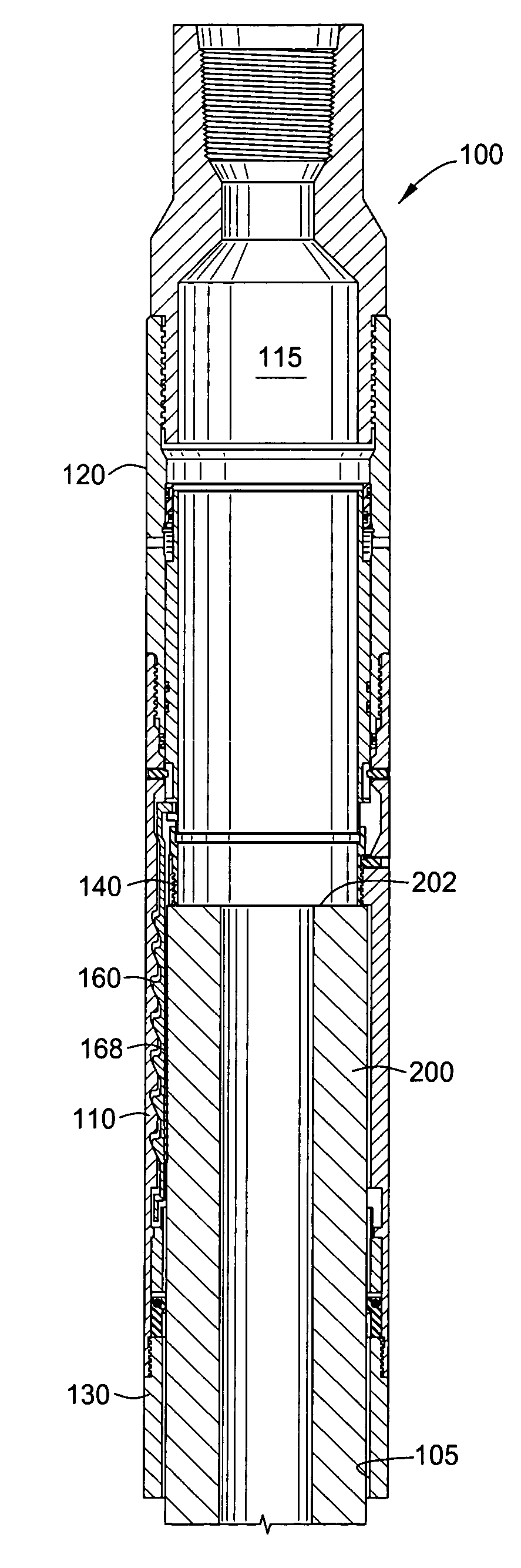
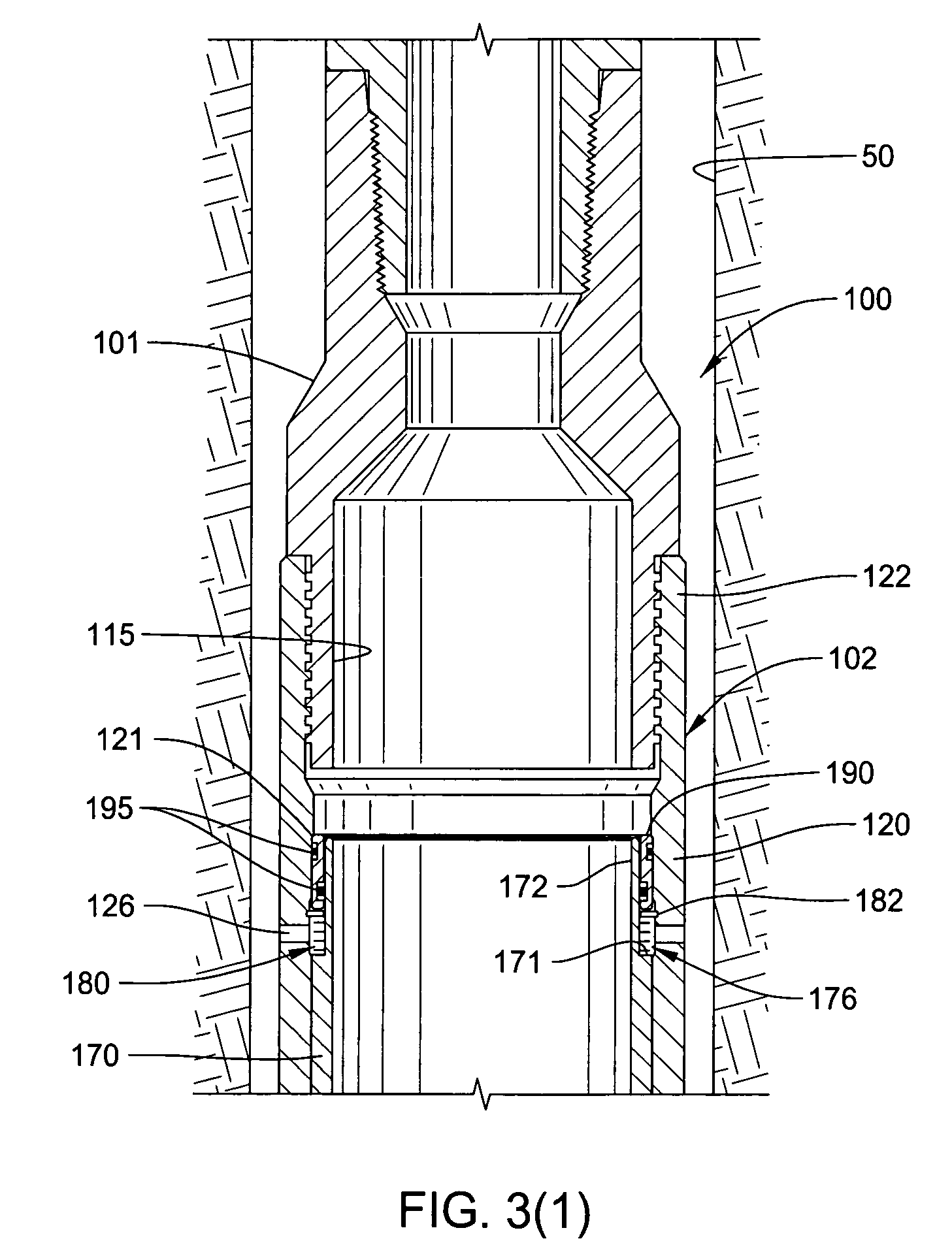
[0037]FIG. 3 presents a cross-sectional view of an overshot tool 100 of the present invention, in one embodiment. For clarification, the view is broken into FIG. 3(1) and FIG. 3(2). The overshot tool 100 is in its “run-in” position. In this respect, the tool 100 is capable of being run into a wellbore 50 in order to retrieve a cylindrical item 200 downhole. The top end of the cylindrical item 200 can be seen in the view of FIG. 3(2), beginning to be received within a bore 115 of the overshot tool 100.

[0038]The overshot tool 100 generally defines an elongated tubular body having an upper end 102, a lower end 104, and a bore 115 formed there between. It is understood that the terms “upper end” and “lower end” are for ease of reference only, and that the tool has utility both in vertical and in laterally or horizontally drilled wellbores. Thus, “upper end” simply refers to the end of the tool 100 most closely connected to the work string, while “lower end” refers to the direction of th...


PUM


Abstract

The present invention provides an improved hydraulic overshot tool. The overshot tool mechanically engages a cylindrical body downhole attempting to be retrieved. In the event retrieval is unsuccessful, the overshot tool may be hydraulically released from the cylindrical body. The release function employs a pressure differential within the overshot tool, but without necessity of a nozzle within the bore of the tool.

Description

BACKGROUND OF THE INVENTION[0001]1. Field of the Invention[0002]The present invention relates to retrieval tools. More specifically, the present invention pertains to overshot tools used for retrieving a cylindrical body that has become lodged or otherwise lost within a wellbore.[0003]2. Description of the Related Art[0004]In the formation of a hydrocarbon or other wellbore, a cylindrical hole is formed vertically through a series of earth formations. Typically, the wellbore is first formed by rotating a drill bit downward at the lower end of a drill string. Traditionally, the drill string has been lowered into the wellbore by threadedly connecting a series of pipe joints, and then rotating those pipe joints in order to impart rotational movement to the drill bit downhole.[0005]During the drilling of a wellbore, it is not uncommon for the operator of the rig to lose the ability to rotate the drill bit downhole. In this respect, those of skill in the art will understand that wellbore...

Claims


Application Information

Patent Timeline
IPC IPC(8): E21B31/18E21B23/04
CPCE21B31/18E21B23/04E21B31/20E21B23/042
Inventor LEMAN, MICHAEL E.VUYK, JR., ADRIAN
Owner WEATHERFORD TECH HLDG LLC
Why Eureka
Try Eureka