Antenna with polarization diversity

a technology of polarization diversity and antennas, applied in the direction of polarisation/directional diversity, individually energised antenna arrays, polarised antenna unit combinations, etc., can solve the problems of large and rather impractical antennas that offer limited reception quality, and achieve small and inexpensive antennas, reliable and quality reception

Inactive Publication Date: 2006-08-01
THOMSON LICENSING SA
View PDF8 Cites 8 Cited by
  • Summary
  • Abstract
  • Description
  • Claims
  • Application Information

AI Technical Summary

Benefits of technology

[0005]The invention proposes a small and inexpensive antenna, particularly for portable televisions, providing reliable and quality reception by polarization diversity.
[0007]With this arrangement, it is easy to obtain a fourth-order polarization diversity (horizontal polarization, vertical polarization, polarizations at + / −45°) to improve the antenna's link budget and, above all, to avoid fading of the reception signal in a given direction. It is also possible to obtain a higher order polarization diversity by introducing a phase shift at the ports that is different from 0 or 180°.
[0015]According to a further feature of the invention, an antenna advantageously comprises a balanced low-noise amplifier linked to the broadband switching and phase shifting circuit via a matching circuit designed to offset matching losses in the bottom part of the antenna's receive spectrum resulting from the miniaturization of the antenna. This matching circuit therefore enables the size of an antenna as described above to be reduced further, while retaining good performance from the radiofrequency point of view, so making it even more functional in its application to indoor portable televisions for terrestrial digital reception. A simple implementation of the matching circuit comprises a high-pass network designed to control the matching of the low-noise amplifier in the antenna's degraded frequency domain and a passive phase shifting circuit designed to control the maximum amplitude of mismatches throughout the antenna's useful frequency band, the passive phase shifting circuit possibly consisting of a microstrip line. Moreover, the balanced low-noise amplifier advantageously comprises hybrid couplers at the input and at the output in order to isolate the matching and noise figure parameters.

Problems solved by technology

Despite the robustness of OFDM (Orthogonal Frequency Division Multiplex) multi-carrier modulation compliant with the DVB-T (Digital Video Broadcast Terrestrial) standard chosen for the transmission of digital channels, measurement campaigns have revealed reception problems, particularly in the context of portable television reception.
These large and rather impractical antennas offer limited reception quality.

Method used


Image

  • Antenna with polarization diversity
  • Antenna with polarization diversity
  • Antenna with polarization diversity

Examples


Embodiment Construction

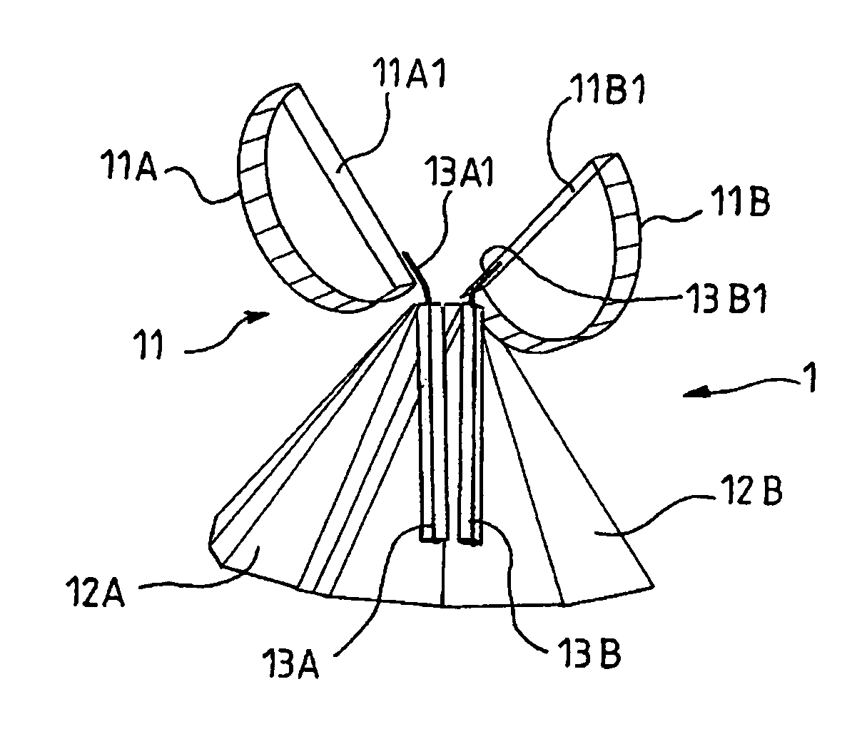
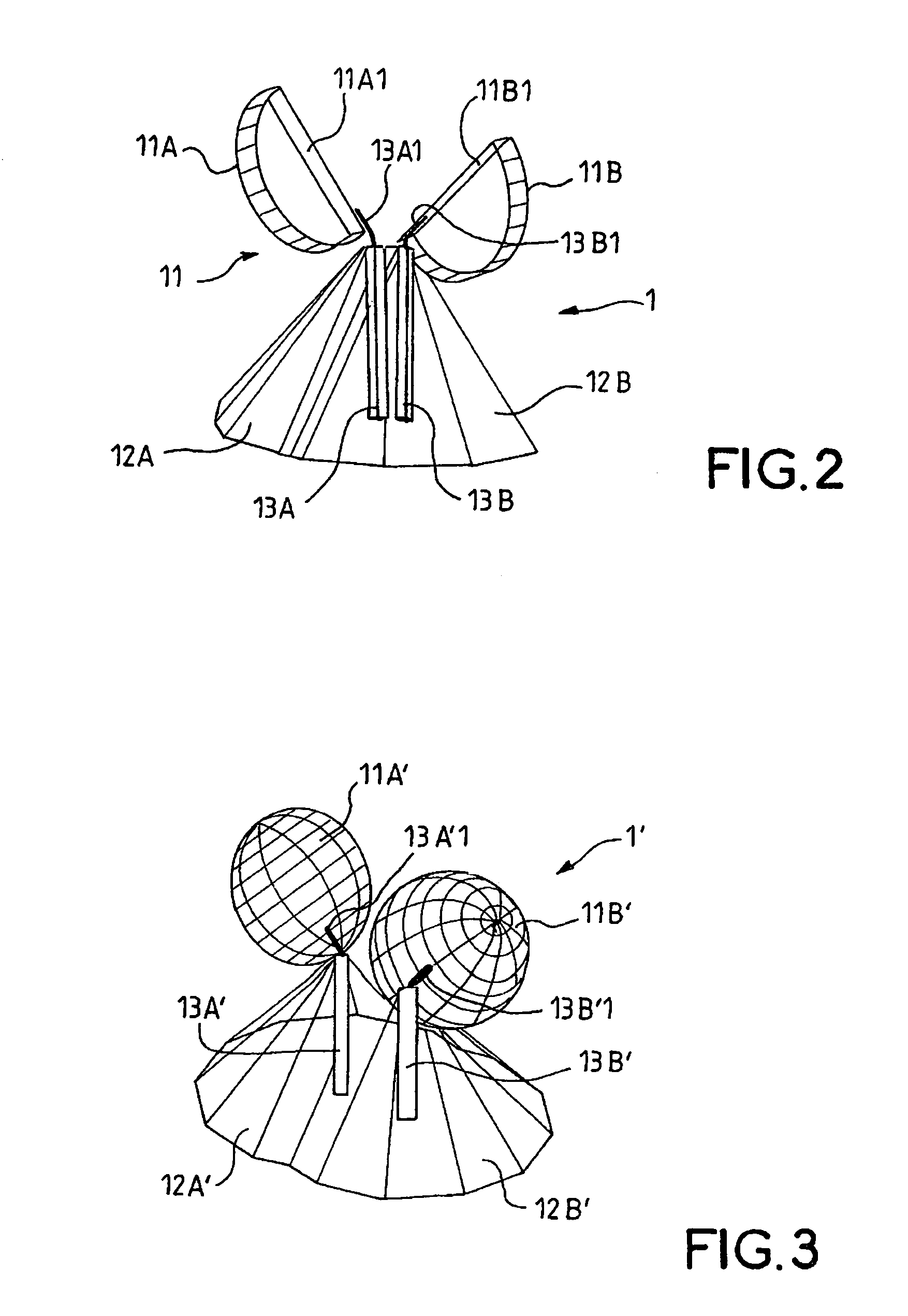
[0025]An antenna according to the invention comprises two ports coupled to a radiating element in such a way that they are placed on the radiating element at 90° to each other and at 45° to a horizontal plane which enables a polarization diversity signal to be supplied via a controlled broadband switching and phase shifting means (electronic circuit) linked to the ports.

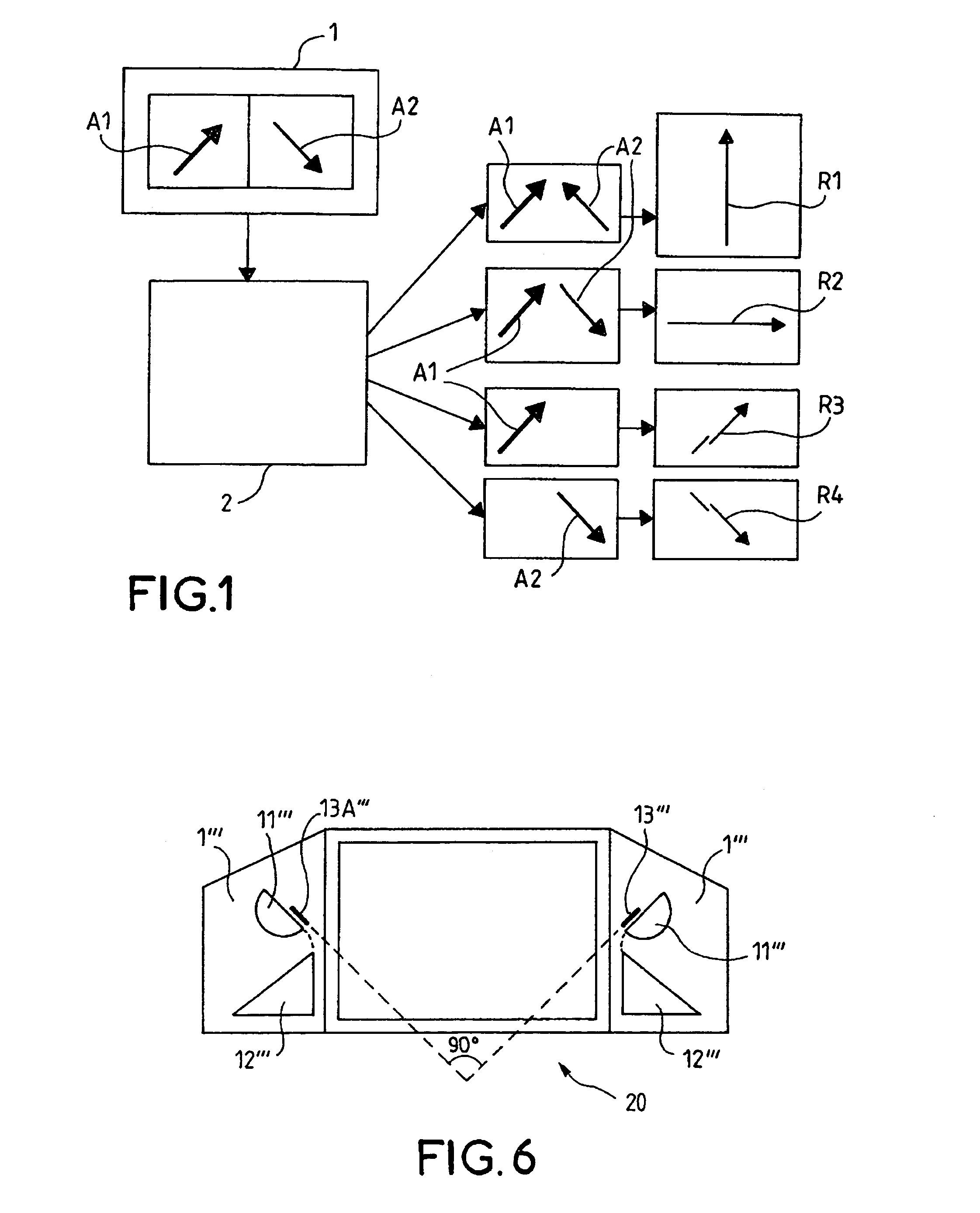
[0026]FIG. 1 very schematically shows the signals A1 and A2 produced by the two ports of the antenna according to the invention, each polarized respectively at +45° and −45°. The direction and the inclination of the arrows shown on FIG. 1 represent the orientation of the polarization. The antenna is symbolized by the rectangle 1. These signals A1, A2 are sent to an electronic circuit or broadband switching and phase shifting block 2 designed to be controlled to combine the signals A1 and A2 in such a way as to produce here, selectively, as output, a resultant signal according to four polarization states, vertical, ho...


PUM


Abstract

The antenna, particularly for portable televisions, comprises two ports coupled to a radiating element (11), the two ports being placed on the radiating element at 90° to each other and at 45° relative to a horizontal plane. The two ports are linked to a broadband switching and phase shifting circuit controlled in order to supply a polarization diversity signal as output.

Description

[0001]The present invention relates to an antenna with polarization diversity particularly for portable televisions. The invention is relevant in particular to the future deployment of the TAT (terrestrial digital television) network.BACKGROUND OF THE INVENTION[0002]Despite the robustness of OFDM (Orthogonal Frequency Division Multiplex) multi-carrier modulation compliant with the DVB-T (Digital Video Broadcast Terrestrial) standard chosen for the transmission of digital channels, measurement campaigns have revealed reception problems, particularly in the context of portable television reception.[0003]Unlike an analogue signal in which the degradation is gradual, a fading phenomenon affecting the digital signal at a given time, over a given area, generates a rapid transition from quality reception to total loss of signal. The result is that the launch of the DVB-T programme is dependent on devising technical solutions for antennas to allow quality reception.[0004]In the context of t...

Claims


Application Information

Patent Timeline
Patent Type & Authority Patents(United States)
IPC IPC(8): H01Q3/24H01Q21/06H01Q1/24H01Q9/38H01Q9/40H01Q21/24H04B7/10
CPCH01Q9/40H04B7/10H01Q21/245H01Q1/24H01Q21/06
Inventor PINTOS, JEAN-FRANCOISROBERT, JEAN-LUCMOCQUARD, OLIVIERLOUZIR, ALITHUDOR, FRANCK
Owner THOMSON LICENSING SA
Why Eureka
Try Eureka