Signal receiving apparatus

a technology of signal receiving apparatus and antenna, which is applied in the field can solve the problems of difficult use, restricted mounting spot, and difficult use of the above-mentioned antenna in this type of signal receiving apparatus, and achieve the effect of small antenna, small and inexpensive antenna, and substantial reduction of the length of the printed radiating conductor

Active Publication Date: 2005-11-03
ALPS ALPINE CO LTD
View PDF1 Cites 10 Cited by
  • Summary
  • Abstract
  • Description
  • Claims
  • Application Information

AI Technical Summary

Benefits of technology

[0013] The present invention is designed to solve the above-mentioned problems, and it is an object of the present invention to provide a signal receiving apparatus in which circularly polarized wave signals of radio signals can be effectively received by properly selecting arrangement shape of an antenna pattern, and of which size is small and of which price is low by use of the antenna pattern.
[0020] As described above, in the signal receiving apparatus according to the aspect of the invention, a receiving circuit board is provided in which the signal receiving circuit is formed on one end of the insulating substrate, the wide pattern and the printed radiating conductor are formed on the other side of the insulating substrate, and the input stage of the signal receiving circuit, the output stage of the printed radiating conductor, and the wide conductive pattern are conductively connected, and the printed radiating conductor and the conductive pattern, serving as an antenna, provide the received signals to the signal receiving circuit through a conductive connection point. Therefore, with the wide conductive pattern cooperating with the printed radiating conductor, it is possible to receive the horizontally polarized wave signal and the vertically polarized wave signal of the radio signal, and accordingly the signal receiving apparatus having a small and inexpensive antenna can be obtained.
[0021] Further, in the signal receiving apparatus according to the aspect of the invention, the SAW filter is arranged on the one side of the insulating substrate, and one end of the SAW filter is connected to the output stage of the printed radiating conductor and the other end of the SAW filter is connected to the input stage of the signal receiving circuit, respectively, so that unnecessary signal components transferred from the printed radiating conductor to the signal receiving circuit can be blocked and thus the signal leakage can be reduced.
[0023] Moreover, in the signal receiving apparatus according to the aspect of the invention, the printed radiating conductor is formed in a winding shape, so that the length of the printed radiating conductor is substantially reduced and thus a small antenna can be obtained.
[0024] In addition, in the signal receiving apparatus according to the aspect of the invention, the arrangement of the conductive pattern and the printed radiating conductor formed on the insulating substrate is properly selected and the circularly polarized wave radio signal can act as an antenna pattern, so that the small and inexpensive antenna can be obtained.
[0025] Further, in the signal receiving apparatus according to the aspect of the invention, the signal receiving circuit is used to receive the radio signal including the detection signal obtained by the tire pressure sensor that detects the tire pressure of the vehicle, and the receiving circuit board is mounted on the vehicle such that directivity of the radio signal received by the receiving circuit board is in a direction connecting a grounded surface of the tire to the uppermost portion thereof, so that the receiving directivity of the antenna of each signal receiving circuit is in a range where only the corresponding radio signal transmitter is placed in sight all the time. Thus, the signal receiving circuit having high accuracy, when receiving the radio signal, can be obtained.

Problems solved by technology

To this end, although these signal receiving apparatuses do not need to use an antenna having high receiving sensitivity as disclosed in the above-mentioned Japanese Unexamined Patent Application Publication No. 11-355022, if the antenna having high receiving sensitivity is used like this, the mounting spot is restricted when mounting the signal receiving apparatuses on the vehicle as well as it is difficult to use when the receiving sensitivity is too high.
Therefore, it is difficult for the above-mentioned antenna to be used in this type of signal receiving apparatus.
For this reason, when the radio signal transmitter is placed in a predetermined range and direction with respect to the signal receiving apparatus, the receiving sensitivity of the antenna with respect to the radio signal transmitted from the radio signal transmitter is increased and thus the signal receiving apparatus may correctly receive the radio signal, however, in a moment that radio signal transmitter is out of the range with respect to the signal receiving apparatus, the receiving sensitivity of the antenna with respect to the radio signal transmitted from the radio signal transmitter is decreased and thus the signal receiving apparatus may not correctly receive the radio signal, so that it is difficult for the antenna described above to be used in this type of signal receiving apparatus.

Method used


Image

  • Signal receiving apparatus
  • Signal receiving apparatus
  • Signal receiving apparatus

Examples


Embodiment Construction

[0030] Hereinafter, an exemplary embodiment of the present invention will be described with reference to the accompanying drawings.

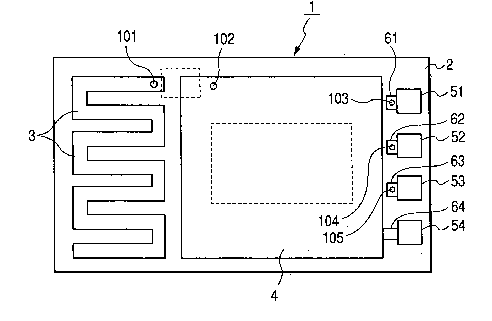
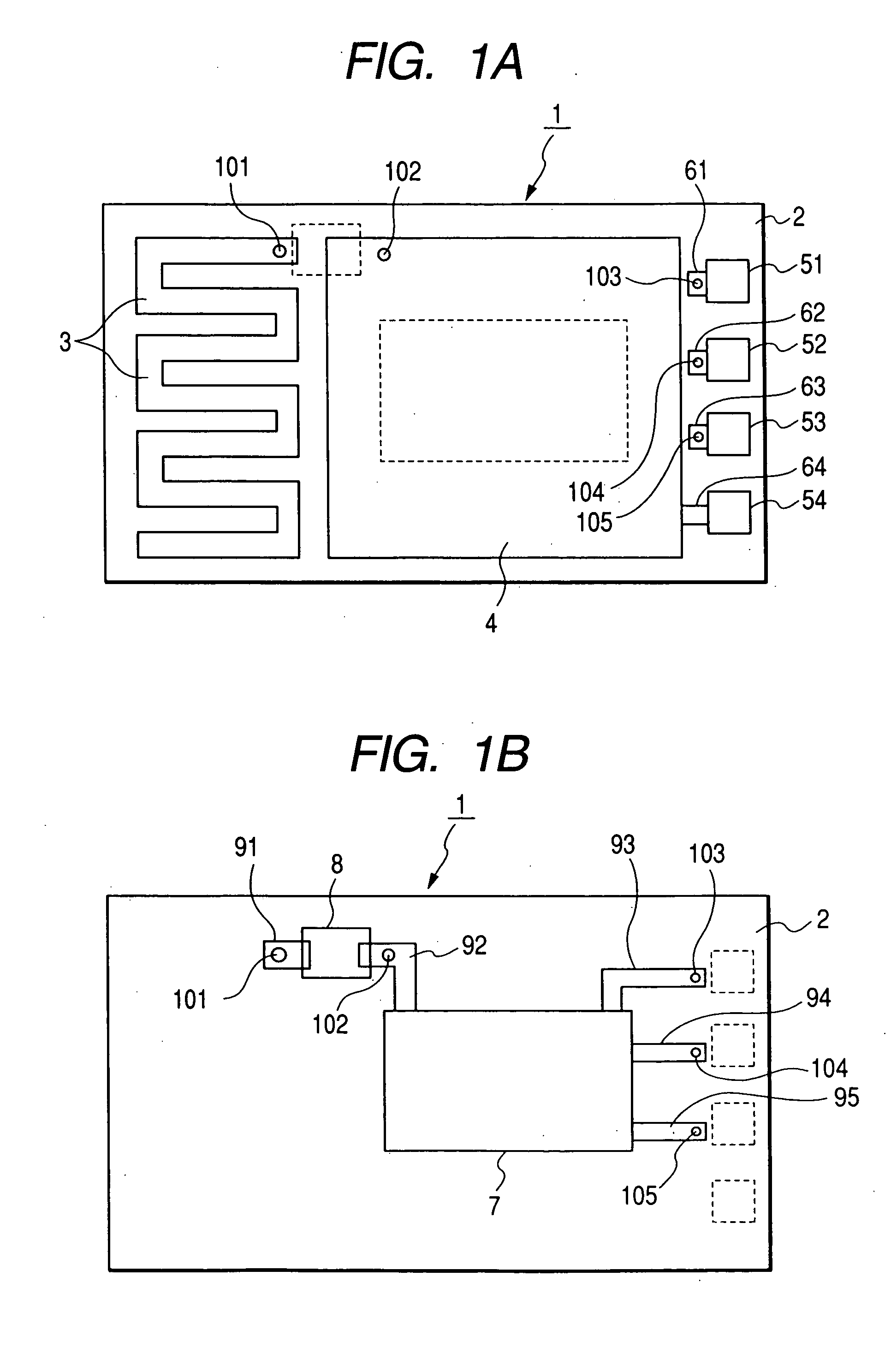
[0031]FIGS. 1A and 1B are plan views showing schematic configurations of a receiving circuit board of a signal receiving apparatus according to an embodiment of the invention, in which FIG. 1A is a configuration of one side thereof and FIG. 1B is a configuration of the other side thereof.

[0032] As shown in FIGS. 1A and 1B, in a receiving circuit board 1 used for the signal receiving apparatus according to the embodiment, on one surface of the insulating substrate 2, a printed radiating conductor 3 formed in a winding shape, a wide conductive pattern 4, four chip bead filters 51, 52, 53 and 54, three connection patterns 61, 62 and 63 respectively extending from three chip bead filters 51, 52 and 53, and one connection pattern 64 extending from one chip bead filter 54 to the wide conductive pattern 4 are arranged.

[0033] In addition, on the other side of...


PUM


Abstract

A signal receiving apparatus includes a receiving circuit board having a signal receiving circuit formed on one side of an insulating substrate, a wide conductive pattern formed on the other side of the insulating substrate that faces a forming position of the signal receiving circuit, and a printed radiating conductor formed on the other side of the insulating substrate deviated from a position that faces the forming position of the signal receiving circuit. In the signal receiving apparatus, an input stage of the signal receiving circuit, an output stage of the printed radiating conductor, and the wide conductive pattern are conductively connected on the receiving circuit board, and received signals are supplied to the signal receiving circuit, by using the printed radiating conductor and the wide conductive pattern as an antenna, through a conductive connection point thereof.

Description

BACKGROUND OF THE INVENTION [0001] 1. Field of the Invention [0002] The present invention relates to a signal receiving apparatus suitable for use in an in-vehicle apparatus of a remote keyless entry (RKE), and more specifically, to a signal receiving apparatus in which, when a receiving circuit board having an antenna pattern thereon is provided, the antenna pattern is formed such that circularly polarized radio wave signals can be received, thereby obtaining a small and light signal receiving apparatus. [0003] 2. Description of the Related Art [0004] Conventionally, a remote keyless entry includes one or more portable transmitters that users individually keep and one or more in-vehicle receivers mounted on a vehicle. With control of any of the portable transmitters, radio signals are transmitted from the portable transmitter, and when the in-vehicle receiver receives the radio signal, the in-vehicle receiver checks whether the portable transmitter that transmitted an ID code inclu...

Claims


Application Information

Patent Timeline
Patent Type & Authority Applications(United States)
IPC IPC(8): E05B49/00B60N5/00G08B13/14H01Q1/22H01Q1/24H01Q1/38H01Q1/44H01Q13/08H01Q23/00H04B1/08H05K1/02
CPCB60R25/24B60N5/00
Inventor SHIBATA, ETSUYAYANAGIMOTO, HIDEKI
Owner ALPS ALPINE CO LTD
Why Eureka
Try Eureka