Compact pulse stretcher

a compact, stretcher technology, applied in the direction of printers, instruments, electrical equipment, etc., can solve the problems of limited space available for projection optical systems with lithographic tools, difficult design of optical components used in microlithography, frequent replacement of optical components,

Inactive Publication Date: 2006-08-01
ASML HLDG NV
View PDF4 Cites 10 Cited by
  • Summary
  • Abstract
  • Description
  • Claims
  • Application Information

AI Technical Summary

Problems solved by technology

A difficulty in designing optical components used in microlithography is caused by the high power density involved during exposure.
The high intensity pulses, over time, damage optical components, such as lenses used in the projection optics, requiring frequent replacement of these optical components.
However, the volume of space available for the projection optical system with the lithographic tool is limited.
Consequently, the volume of space available for the pulse stretcher is also limited, often precluding the use of a large number of cascaded pulse stretchers.
With the conventional designs, the delay is so long that the delay path must be folded many times to fit in a reasonable volume.
This creates alignment difficulties.
Alternatively, many shorter delays can be applied in tandem, but this also requires many mirrors, which are difficult to align.
Also, the limited number of “copies” of the pulse achievable with practical pulse stretcher designs leaves sharp peaks in the pulse profile.

Method used


Image

  • Compact pulse stretcher
  • Compact pulse stretcher
  • Compact pulse stretcher

Examples


Embodiment Construction

[0021]Reference will now be made in detail to the embodiments of the present invention, examples of which are illustrated in the accompanying drawings.

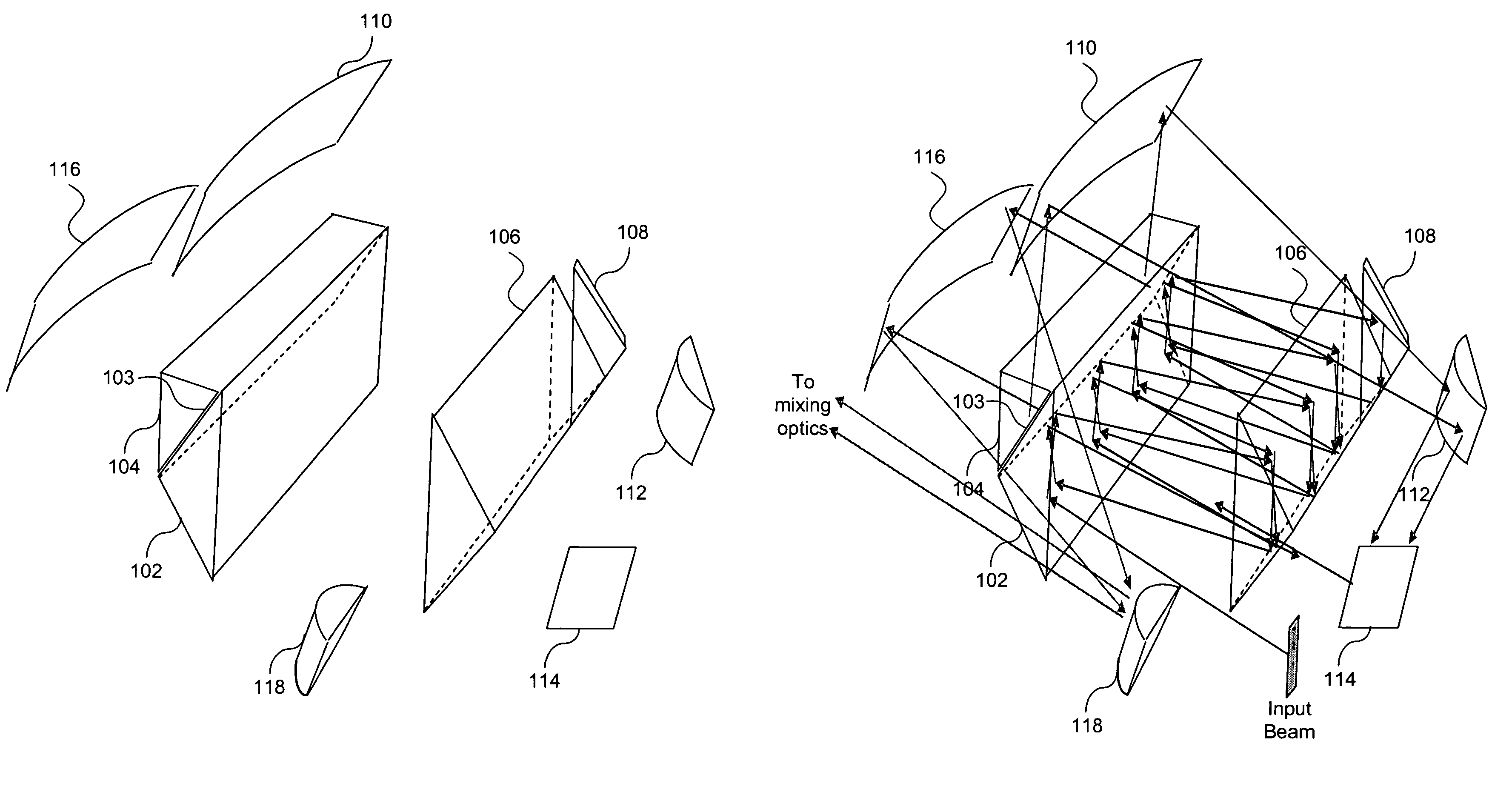
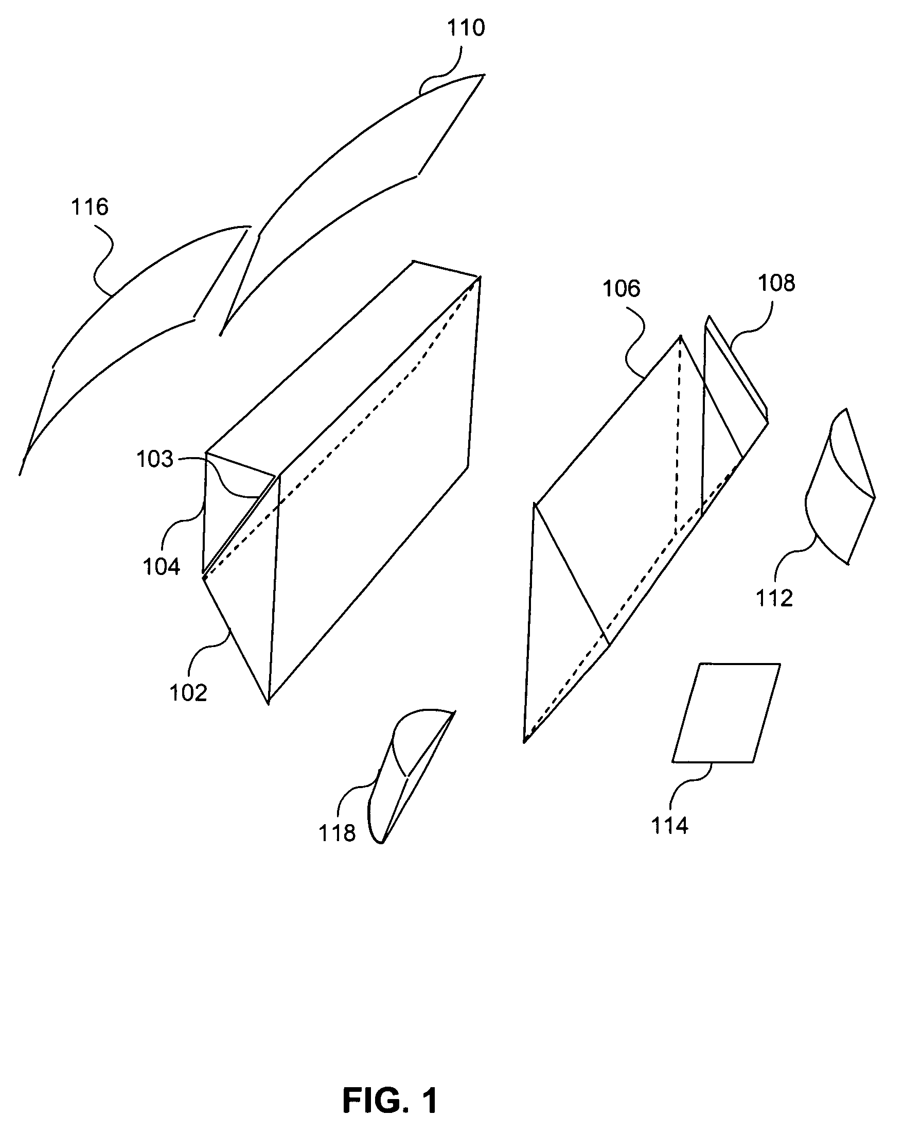
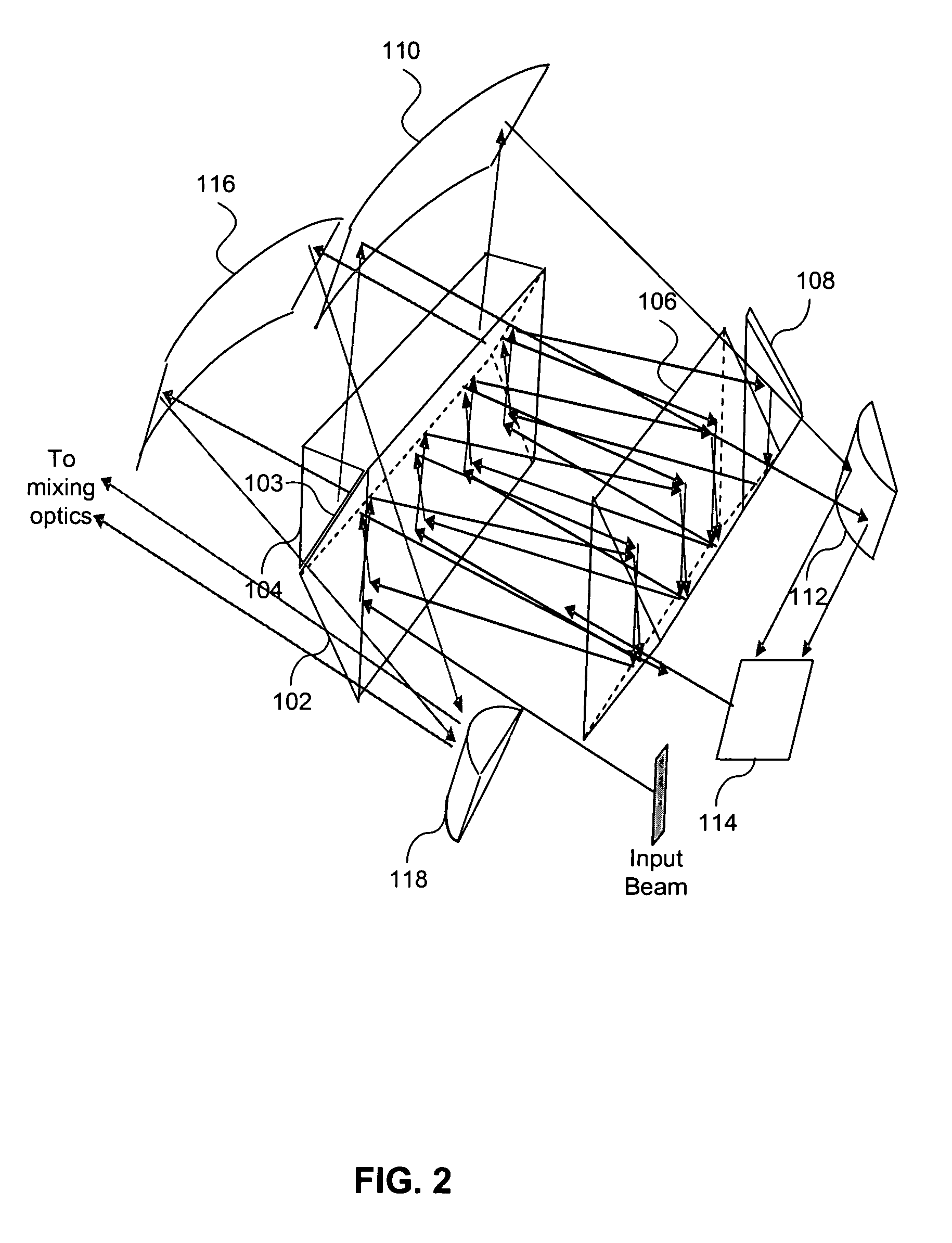
[0022]To achieve a compact pulse stretcher, two prisms (or a single cube) can be used to fold an input beam into a loop that constitutes the delay path. By angling the input beam in the third dimension orthogonal to the plane of the loop, the beam follows a shallow helical path, thus allowing the same delay optics to be used several times. As many as four possible independent helical paths through the delay loop may be obtained by reintroducing the beam with the optics, and a single compact set of delay optics with a relatively small delay per each loop can effectively provide a very long delay. A coupling prism on one face extracts a small part of the beam at each loop, producing many delayed pulses that result in both stretching and smoothing of the pulse. The pulses are also spatially separated, but can be mixed back together by an...


PUM

PropertyMeasurementUnit
lengthaaaaaaaaaa
lengthaaaaaaaaaa
sizeaaaaaaaaaa

Abstract

A pulse stretcher includes a first prism and a second prism positioned opposite each other. A first coupling prism is optically coupled to the first prism with a partially reflective interface that directs a beam towards the second prism in a helical path. The first prism and the first coupling prism form a beamsplitter. A recirculating prism (or a reflective element) reflects the beam from the first prism into the second prism. Mirrors are positioned around the first and second prisms to permit recirculation of the beam through the first and second prisms. The beam recirculates through the first and second prisms using two or more helical paths. The pulse stretcher can be incorporated into a lithographic system.

Description

BACKGROUND OF THE INVENTION[0001]1. Field of the Invention[0002]The present invention is related to pulse stretchers, and more particularly, to pulse stretchers for use in lithographic systems.[0003]2. Related Art[0004]Lithography is a process used to create features on the surface of substrates. Such substrates can include those used in the manufacture of flat panel displays (e.g., liquid crystal displays), circuit boards, various integrated circuits, and the like. A frequently used substrate for such applications is a semiconductor wafer or glass substrate.[0005]During lithography, a wafer, which is disposed on a wafer stage, is exposed to an image projected onto the surface of the wafer by exposure optics located within a lithography apparatus. While exposure optics are used in the case of photolithography, a different type of exposure apparatus can be used depending on the particular application. For example, x-ray, ion, electron, or photon lithography each can require a differe...

Claims


Application Information

Patent Timeline
Patent Type & Authority Patents(United States)
IPC IPC(8): G03B27/54G01N21/55G03B27/72G03F7/20G02B27/10H01L21/027
CPCG03F7/7055G03B27/72
Inventor ALBERT, MICHAEL M.
Owner ASML HLDG NV
Why Eureka
Try Eureka