Image forming apparatus

a technology of forming apparatus and forming chamber, which is applied in the direction of electrographic process apparatus, instruments, optics, etc., can solve the problems of difficult visual positioning, difficult to remove the thus stopped sheet-like recording member, and the operation must be stopped immediately, so as to achieve efficient jam handling and improve the efficiency of jam handling, the effect of increasing the number of components

Inactive Publication Date: 2006-08-01
K MIZRA LLC
View PDF11 Cites 16 Cited by
  • Summary
  • Abstract
  • Description
  • Claims
  • Application Information

AI Technical Summary

Benefits of technology

[0014]In view of the above situation, an object of the invention is to provide an image forming apparatus that can accomplish jam handling efficiently without increasing the number of components and without increasing the manufacturing and assembly costs. Another object of the invention is to provide an image forming apparatus that further improves the jam handling efficiency by reducing the attractive force between transfer carrier and sheet-like recording member as much as possible.

Problems solved by technology

As a result, when any one of the sheet-like recording members being transported in succession gets jammed, causing an emergency stop of the image forming apparatus, in many cases the sheet-like recording members remain stopped between the transfer carrier and the image carriers.
In particular, if a transport jam occurs in the fixing section, the operation must be stopped immediately.
If a sheet-like recording member stops between the transfer carrier and the image carriers, it is difficult to remove the thus stopped sheet-like recording member by picking it up with fingers, since not only is the sheet-like recording member electrostatically attracted to the transfer carrier, but the transfer carrier is brought into contact with the image carriers.
However, it is difficult to visually locate the sheet-like recording member lying between the transfer carrier and the image carriers; besides, since an image forming apparatus is usually not equipped with means for detecting a sheet-like recording member lying on the transfer carrier, it is difficult for the image forming apparatus itself or the operator to check whether the jammed sheet-like recording member remains attracted to the transfer carrier.
Accordingly, the configuration in which the transfer carrier is driven in the reverse direction whenever a jam occurs has the problem that, if the sheet-like recording member is not on the transfer carrier, the reversing action is of no use and is not only time wasting but also uneconomical.
On the other hand, if a detector for detecting a sheet-like recording member on the transfer carrier is to be installed, there arises the problem that the number of components increases, increasing the manufacturing and assembly costs as well as the overall size of the image forming apparatus.
Accordingly, the force working to attract the sheet-like recording member to the transfer carrier cannot be reduced by merely cutting off the transfer bias as in JP-A 11-119490 cited above, and the attractive force between the transfer carrier and the sheet-like recording member remains high; therefore, there remains the concern that the difficulty in removing the jammed sheet-like recording member cannot be solved with the above arrangement.

Method used


Image

  • Image forming apparatus
  • Image forming apparatus
  • Image forming apparatus

Examples


Embodiment Construction

[0068]Embodiments of an image forming apparatus according to the invention will be described with reference to the accompanying drawings.

(Image Forming Apparatus)

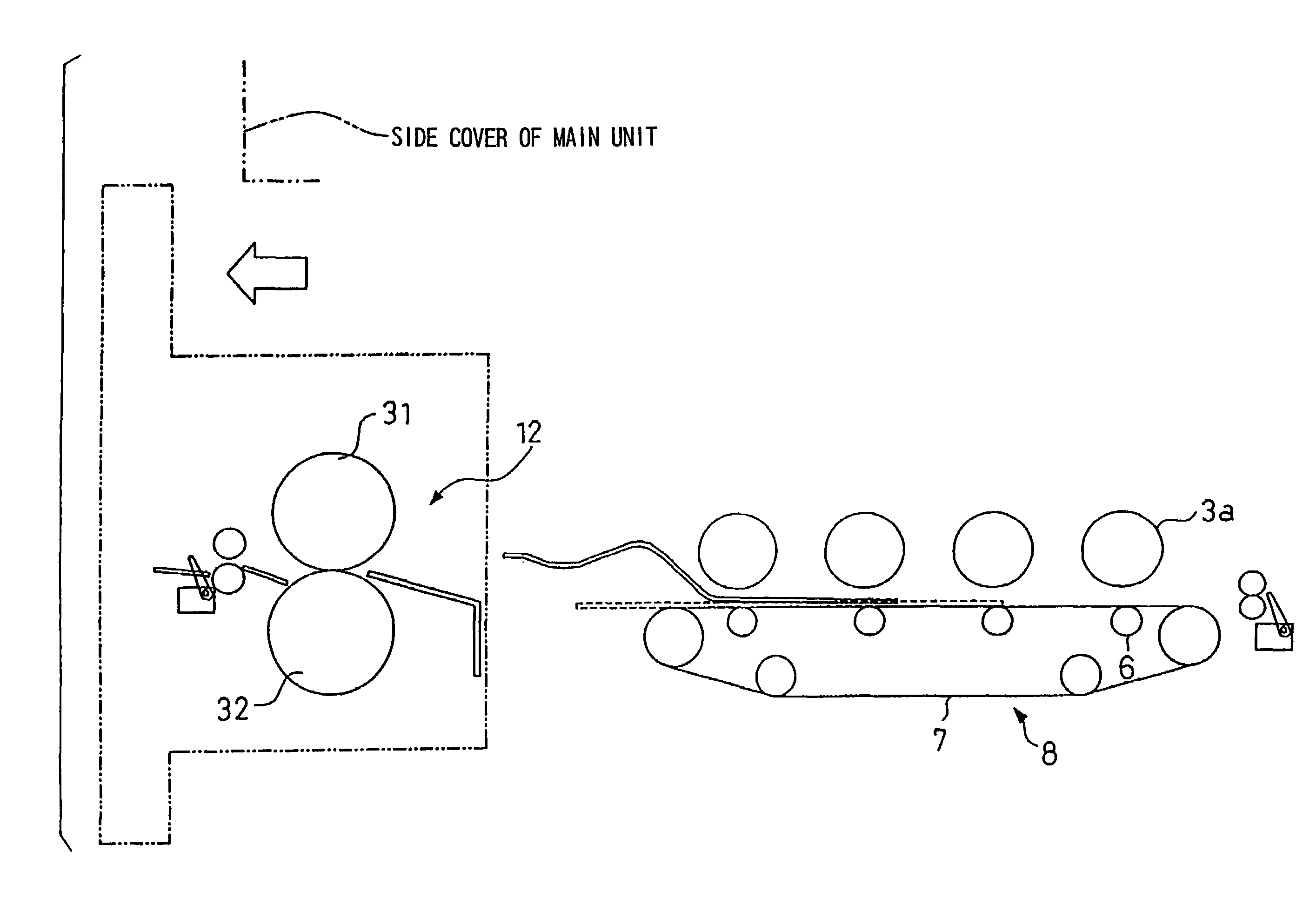
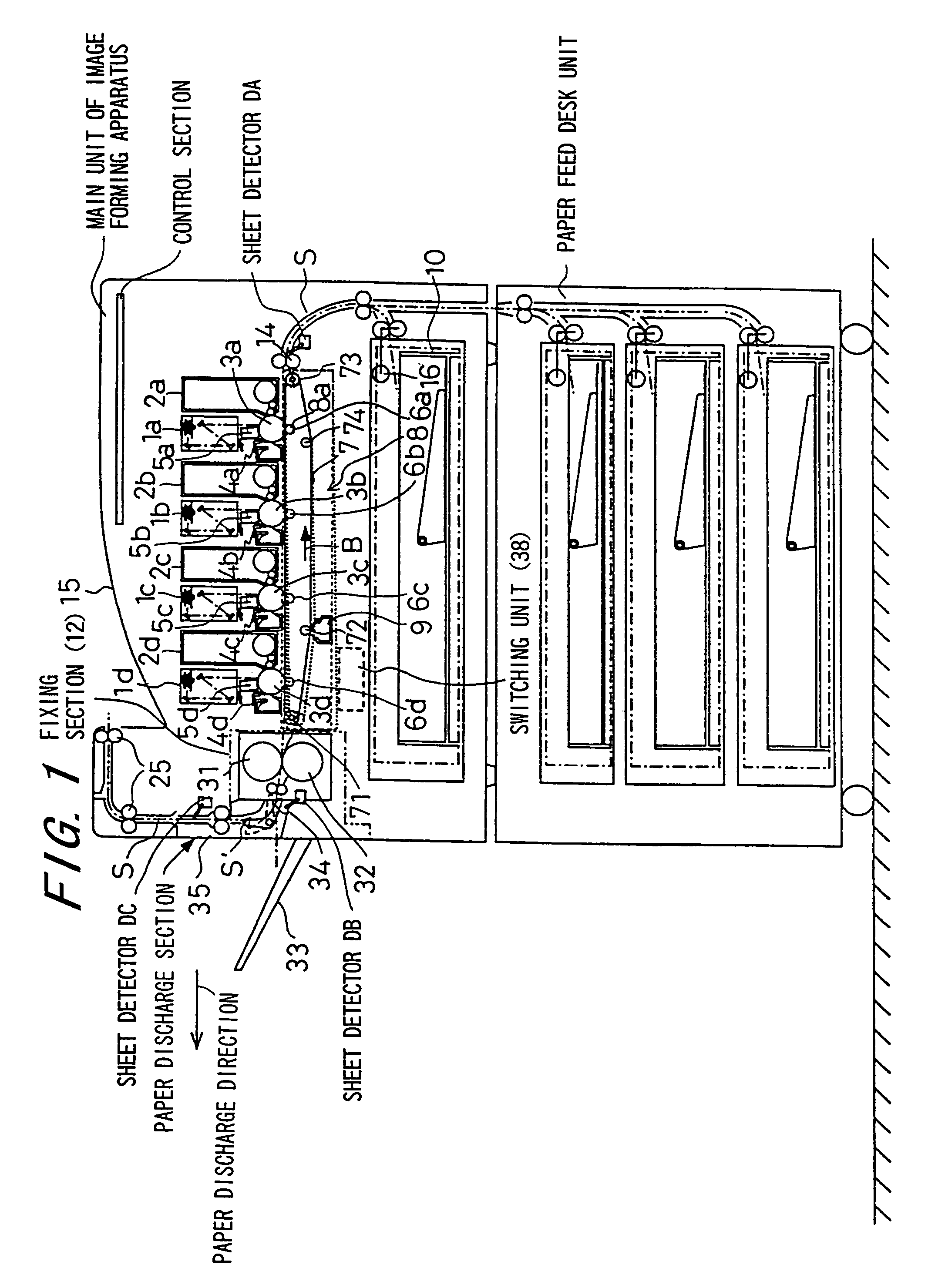
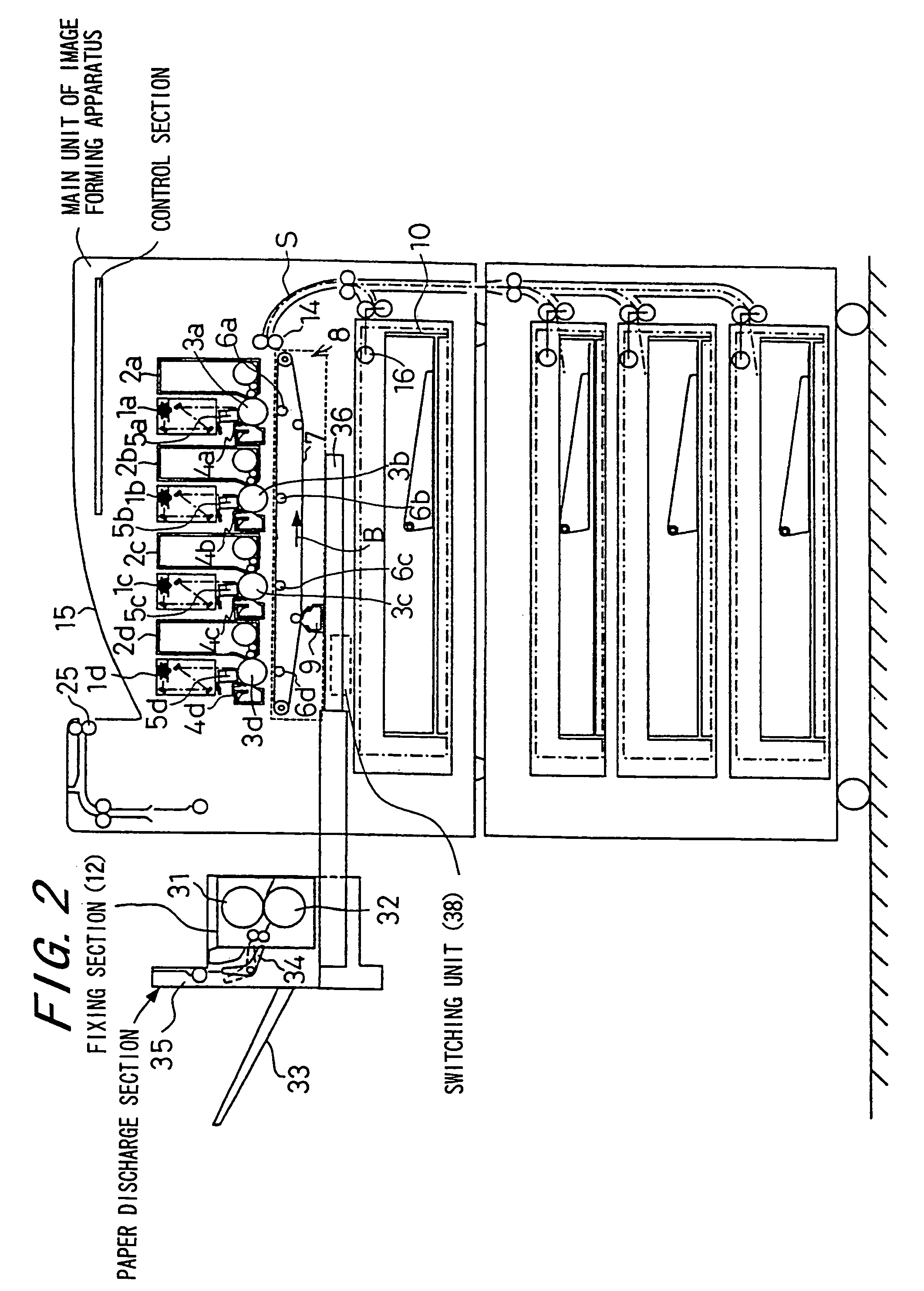
[0069]FIG. 1 shows the construction of an image forming apparatus according to one embodiment of the invention. The image forming apparatus shown here forms a multicolor or single-color image on a prescribed sheet-like recording member (recording paper, hereinafter called the sheet) in accordance with externally supplied image data, and the main unit of the image forming apparatus comprises an exposure unit 1, a developer unit 2, a photoconductor drum 3 as an image carrier, a charge unit 5, a cleaner unit 5, a transfer / transport belt unit 8, a fixing unit 12, a paper transport path S, a paper feed tray 10, and a paper discharge tray 15.

[0070]The image data used in this image forming apparatus are data for forming color images using black (K), cyan (C), magenta (M), and yellow (Y) colors, respectively. Accordingly, the image...


PUM


Abstract

An image forming apparatus transfers a toner image formed on a photoconductor drum onto a sheet-like recording member while the sheet-like recording member is transported and attracted to a transfer belt, and comprises a jam handling control unit for detecting a transport fault of the sheet-like recording member, and for stopping the transport operation when the transport fault is detected. When the transport fault is detected in a section other than a fixing section, the jam handling control unit first causes the transport operation of the fixing section, and thereafter causes the transfer belt and the transport operation on the upstream side thereof to stop, and any sheet-like recording member remaining on the transfer belt so that the transport mechanism on the upstream side thereof is transported and stopped at the position spanning between the area of the fixing section and the area of the transfer belt.

Description

[0001]This is a division of application Ser. No. 10 / 365,376, filed Feb. 11, 2003, now U.S. Pat. No. 6,775,486.BACKGROUND OF THE INVENTION[0002]1. Field of the Invention[0003]The present invention relates to an image forming apparatus, such as a copying machine, printer, fax machine, or the like, for forming various kinds of images on sheet-like recording members, and more particularly to a technique for handling a jam which occurs during transport of sheet-like recording members.[0004]2. Description of the Related Art[0005]Image forming apparatuses are well known in the prior art; in such apparatuses, a toner image formed on an image carrier is transferred to a sheet-like recording member by making the toner image electrostatically adhere to it by a transfer carrier, and thereafter the toner image is affixed onto the sheet-like recording member in a fixing section to accomplish the formation of the image. In a certain type of such image forming apparatuses, in particular, a tandem i...

Claims


Application Information

Patent Timeline
Patent Type & Authority Patents(United States)
IPC IPC(8): G03G15/00G03G21/00G03G15/01G03G15/16
CPCG03G15/70G03G2215/00552
Inventor MATSUYAMA, KAZUHIROTATEISHI, YOSHINOBUMIKITA, TOSHIYAHIRAI, MASASHIYAMANAKA, TOSHIOTERADA, MITSUYOSHINAKAGAWA, YUJIFUJIMOTO, OSAMU
Owner K MIZRA LLC
Why Eureka
Try Eureka