Image forming apparatus

a technology of image forming apparatus and forming apparatus, which is applied in the direction of electrographic process apparatus, instruments, optics, etc., can solve the problems of low productivity of the image forming apparatus above described and disordered latent image formation, so as to prevent latent images, improve productivity, and reduce the effect of productivity

Inactive Publication Date: 2006-08-01
CANON KK
View PDF19 Cites 9 Cited by
  • Summary
  • Abstract
  • Description
  • Claims
  • Application Information

AI Technical Summary

Benefits of technology

[0007]It is an object of the invention to provide an image forming apparatus preventing latent images from formed disorderly due to vibrations occurring when a member contacting to an intermediate transfer body is attached and detached. This invention,. particularly in an image forming apparatus equipped with a plurality of image carriers intending to improve the productivity, to solve the above problems without reducing the productivity.

Problems solved by technology

The image forming apparatus above described does not have high productivity because the intermediate transfer body is required to be rotated the same times as the color number of the overlapped toners to overlap the toner images.
That is, in respect to the members contacting to the intermediate transfer body, attaching and detaching operations are needed during the image forming process, so that vibrations due to attaching and detaching operations may raise a problem rendering latent image formation disordered.

Method used


Image

  • Image forming apparatus
  • Image forming apparatus
  • Image forming apparatus

Examples


first embodiment

[First Embodiment]

[0023]FIG. 1 is for a first embodiment of the invention. Hereinafter, it is dubbed in reference with the drawings.

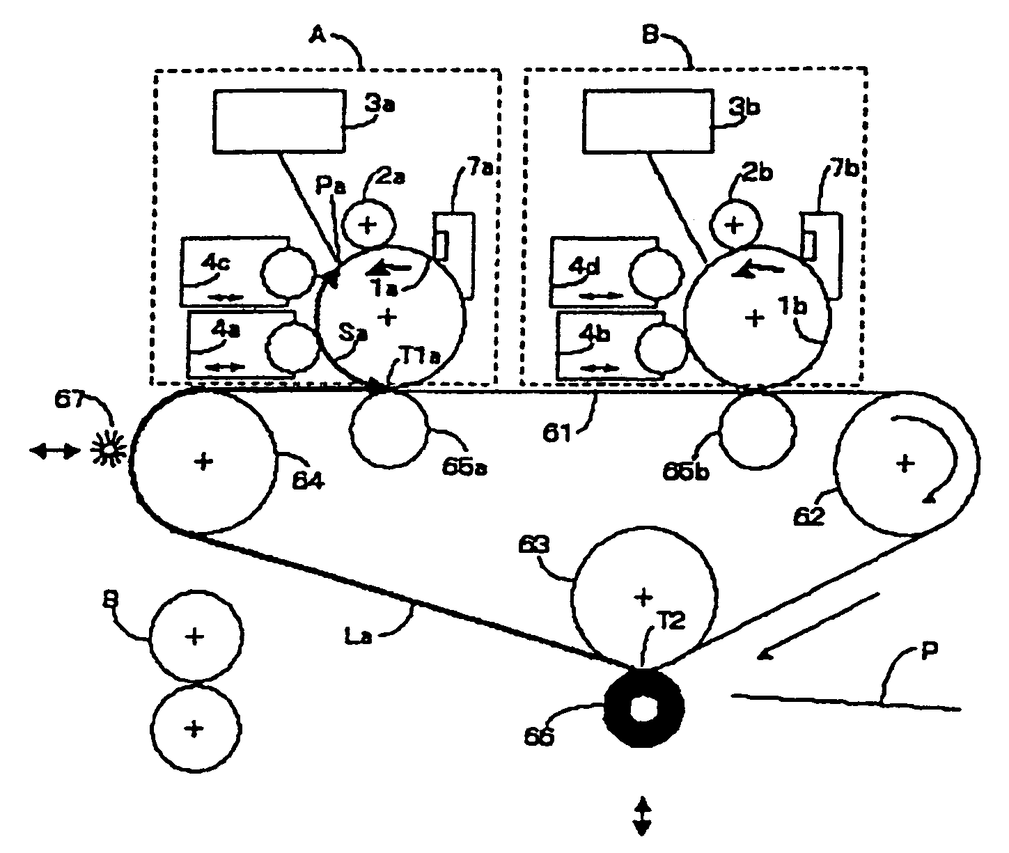
[0024]An image forming apparatus is described below in which a first image forming portion and a second image forming portion are disposed around a movable endless image carrier, in which each image forming portion has at least two switchable developing apparatuses around an electrostatic latent image carrier, in which the two image forming portions do making latent images formed on electrostatic latent image carrier by exposure from an exposing apparatus to be toner images sequentially with the two developing apparatuses to transfer the toner images on the image carrier by a first transferring means, respectively, and in which the plural toner images formed on the image carriers am transferred at once on a recording material with a second transferring mean separably contacting to the image carrier.

[0025]Around an intermediate transfer belt 61 disposed ...

second embodiment

[Second Embodiment]

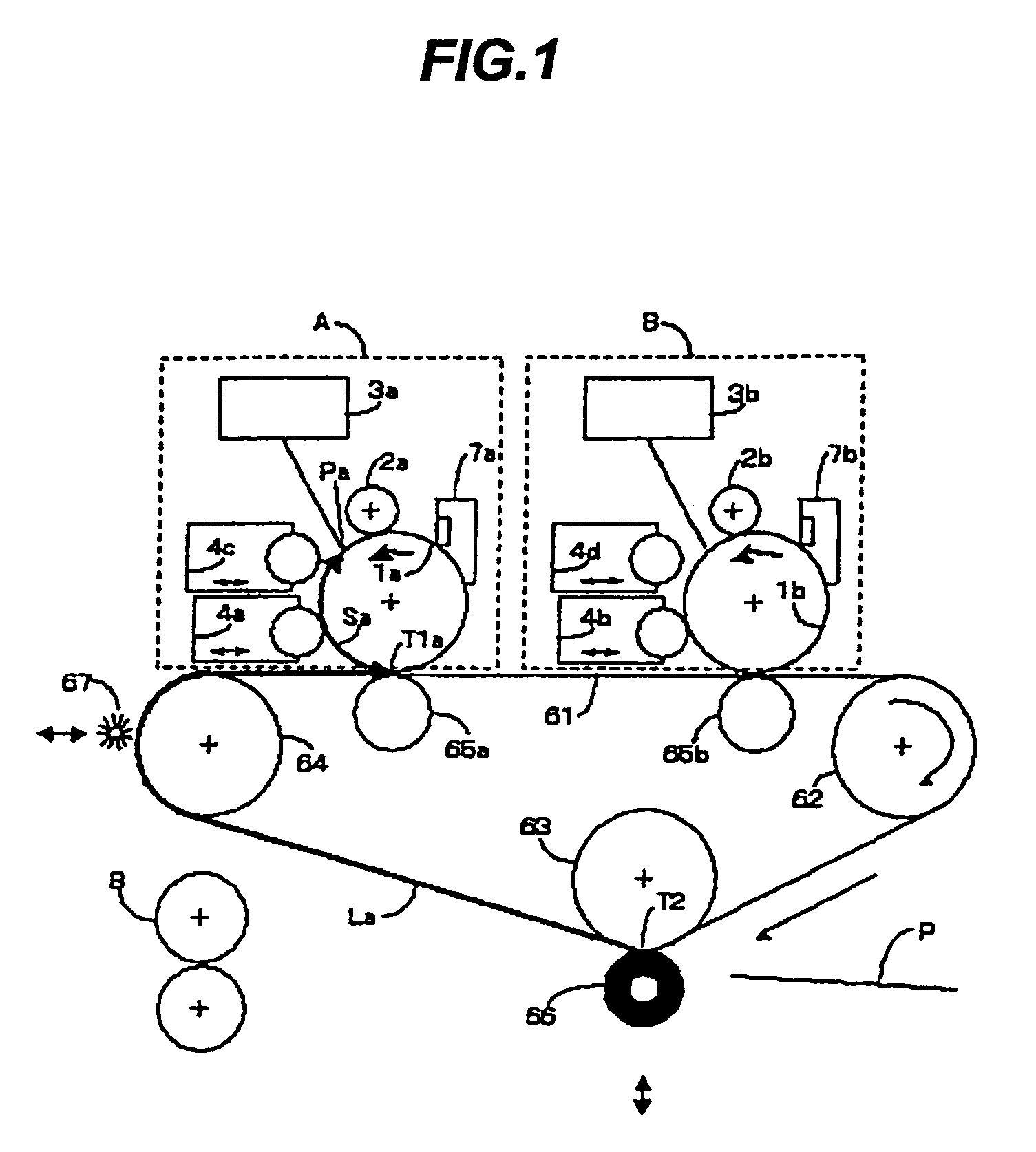
[0038]FIG. 2 is for the second embodiment of the invention. Members having the same structure and function as those in the first embodiment as described above are assigned with the same reference numbers, respectively, as a description is omitted. First embodiment is of a system adapting a fur blushing mechanism as a detachable cleaning means on the intermediate transfer belt 61. The fur blush does cleaning function adequately even where pressing force to the intermediate transfer belt 61 is small, and is workable without generating vibrations such that the latent image formation is greatly affected. In this embodiment, the cleaning means 68 contacting to the intermediate transfer belt 61 adapts a member utilizing a cleaning blade 68a. The cleaning blade 68a is for cleaning upon stagnating the secondary transfer remaining toner on the intermediate transfer belt 61, and the contact force is set 1000 gf, thereby surely functioning cleaning effects. This cleaning bla...

third embodiment

[Third Embodiment]

[0040]FIG. 3 is for the third embodiment of the invention. Members having the same structure and function as those in the first embodiment as described above are assigned with the same reference numbers, respectively, and a description is omitted. In this embodiment, exposure blurs due to contacting shocks from the secondary transfer roller 66 are avoided, and the apparatus is made with a smaller size and reduced costs.

[0041]In this embodiment, the exposure blurs due to contacting shocks from the secondary transfer roller 66 are avoided by rendering, in substantially the same way as in the first embodiment, a distance Sa in the rotational direction of the photosensitive drum 1a from the exposing position Pa to the primary transfer position T1a on the photosensitive drum 1a in the first image forming portion A, a distance La in the moving direction of the intermediate transfer belt 61 from a secondary transfer position T2 on the intermediate transfer belt 61 to a pr...


PUM


Abstract

An image forming apparatus includes a plurality of movable image carriers, a movable intermediate transfer body, and a contacting member separably contacting to the intermediate transfer body at a contacting position. A position for transfer between a first image carrier and the intermediate transfer body defines a first transfer position. A position for transfer between a second image carrier and the intermediate transfer body defines a second transfer position. A toner image formed on said intermediate transfer body is again transferred onto a transfer material after passing through said first transfer position and said second transfer position. The latent image formation on the first image carrier is done at a time different from a contacting operation of the contacting member.

Description

BACKGROUND OF THE INVENTION[0001]1. Field of the Invention[0002]This invention relates to an image forming apparatus such as a printer, photocopier, and a facsimile machine and, more particularly, to an apparatus utilizing an intermediate transfer body.[0003]2. Description of Related Art[0004]As an image forming apparatus of a full color electrophotographic type, an apparatus has been known to form full color images by sequentially forming plural toner images on a single photosensitive body and overlapping those toner images on an intermediate transfer body. More specifically, FIG. 10 illustrates the above structure. Respective toner images are sequentially formed upon sequentially facing developing units 4a, 4b, 4c, 4d having toners in different colors onto a first image carrier 1 as a sole photosensitive drum by means of a developing rotary apparatus 5. The respective color toner images are overlapped sequentially onto an intermediate transfer body 61 from the image carrier 1, and...

Claims


Application Information

Patent Timeline
Patent Type & Authority Patents(United States)
IPC IPC(8): G03G15/16G03G15/01
CPCG03G15/0121G03G15/0184G03G2215/0154G03G15/0173
Inventor SODA, TAKAMITSUTAKEUCHI, AKIHIKOKOBAYASHI, TATSUYAENOMOTO, NAOKISUZUKI, TAKEHIKO
Owner CANON KK
Why Eureka
Try Eureka