Method for changing channel information in digital TV receiver

Inactive Publication Date: 2006-08-01
LG ELECTRONICS INC
View PDF25 Cites 46 Cited by
  • Summary
  • Abstract
  • Description
  • Claims
  • Application Information

AI Technical Summary

Benefits of technology

[0009]An object of the present invention is to provide a method for changing channel information

Problems solved by technology

Because the related art digital TV receiver maintains a channel set at initial power supply as it is during watching a broadcasting, the related art digital TV receiver has a problem in that a channel having no d

Method used


Image

  • Method for changing channel information in digital TV receiver
  • Method for changing channel information in digital TV receiver
  • Method for changing channel information in digital TV receiver

Examples


Embodiment Construction

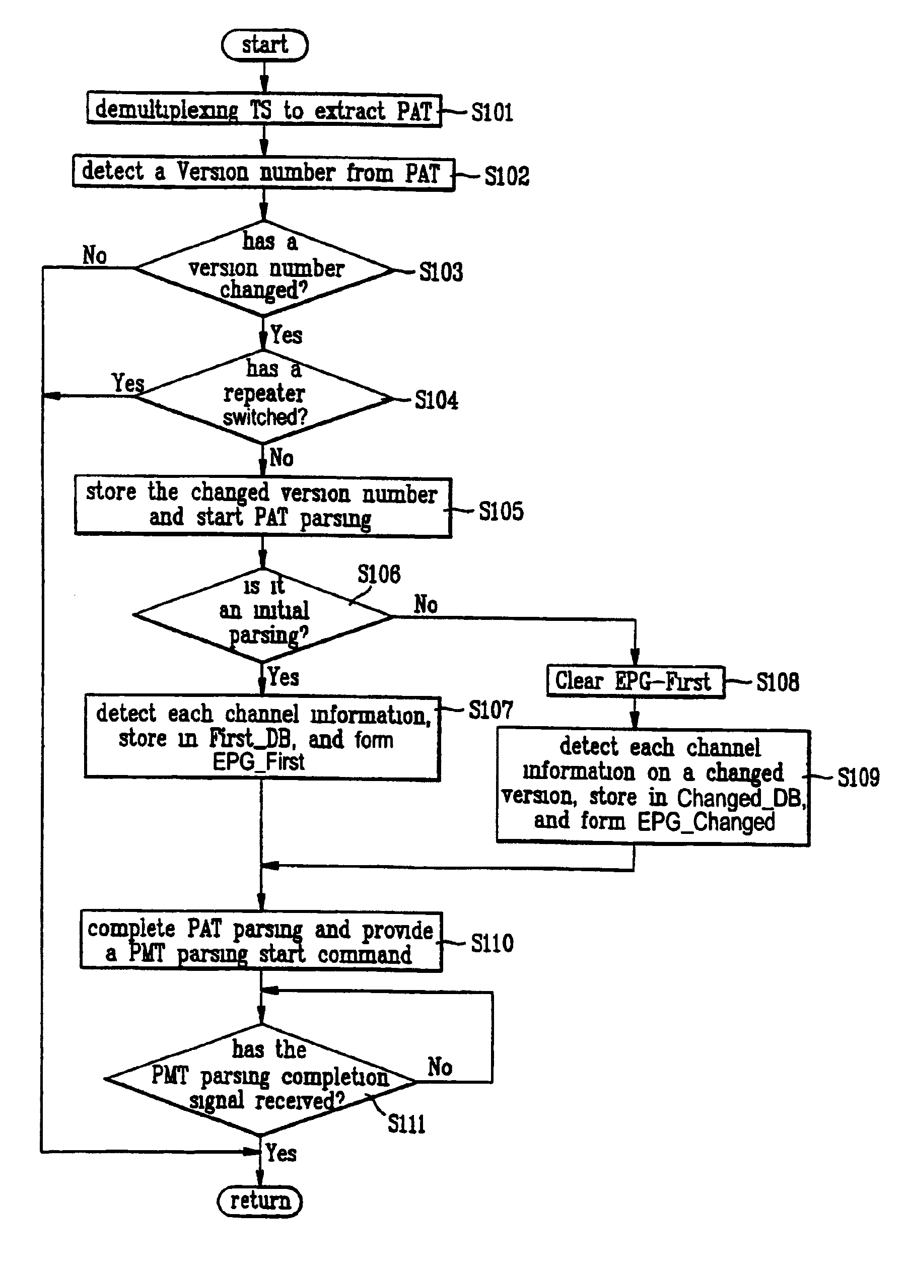
[0023]Reference will now be made in detail to the preferred embodiments of the present invention, examples of which are illustrated in the accompanying drawings. FIG. 4 illustrates flow chart showing the steps of a method for parsing a PAT in changing channel information in a digital TV receiver in accordance with a preferred embodiment of the present invention, FIG. 5 illustrates flow chart showing the steps of a method for parsing a PMT in changing channel information in a digital TV receiver in accordance with a preferred embodiment of the present invention, FIGS. 6a and 6b explain a method for checking canceled / added channel in FIG. 5, FIG. 7 illustrates an embodiment of algorithm for conducting the checking of canceled / added channel in FIG. 5, and FIG. 8 illustrates an embodiment of algorithm for adjusting the channel list in FIG. 6a.

[0024]The method for changing channel information in a digital TV receiver of the present invention is achieved by parsing PAT and PMT in the PSI...


PUM


Abstract

Method for changing channel information in a digital TV receiver which can deal with a channel cancellation/addition during broadcasting, including the steps of (1) determining a channel information of being changed from a broadcasting signal received at every preset time interval and storing the changed channel information, and (2) comparing the stored changed channel information and channel information stored already, for updating the channel information.

Description

BACKGROUND OF THE INVENTION[0001]1. Field of the Invention[0002]The present invention relates to a digital TV receiver, and more particularly, to a method for changing channel information in a digital TV receiver.[0003]2. Background of the Related Art[0004]Recently, keeping pace with development on TV technologies, there has been growing interests in digital TV receivers having a digital transmission system applied thereto, and, in a domestic case, the Mugungwha satellite was launched and started digital test broadcasting in July '96. In general, a time multiplexed signal of video, audio and program specific information signals intended to transmit in a digital satellite broadcasting is called as a transport stream(TS), which is QPSK modulated before transmission to respective receivers through a satellite.[0005]Referring to FIG. 1, in detail, the information multiplexed to TS has an elementary stream of which main purpose is broadcasting, and a RSMS(Resource & Subscriber Management...

Claims


Application Information

Patent Timeline
IPC IPC(8): H04N5/445
CPCH04N5/4401H04N21/235H04N21/4331H04N21/4586H04N21/4345H04N21/435H04N21/434H04N21/426H04N5/50
Inventor PARK, YONG-SEOK
Owner LG ELECTRONICS INC
Why Eureka
Try Eureka