Non-slip bottle opener

a bottle opener and non-slip technology, applied in the field of bottle openers, can solve the problems of the prying elements slipping off the lower edge, the metal bottle caps are not removable by hand, and the conventional bottle cap opener is especially susceptible to slipping

Inactive Publication Date: 2006-08-08
OLEKSY JOHN R
View PDF28 Cites 16 Cited by
  • Summary
  • Abstract
  • Description
  • Claims
  • Application Information

AI Technical Summary

Benefits of technology

[0011]The present invention overcomes the problems cited in the prior by providing a non-slip compact bottle cap opener 100 for removing a bottle cap 40 from a bottle top 10. The opener 100 is formed as a unitary element with its length and thickness similar to length and thickness of a standard key so that it can fit comfortably onto a key ring or key chain with other keys. The opener 100 has a handle portion 105 with which the user applies prying force to the bottle cap with a mechanical advantage. The handle includes a through hole or other attaching arrangement for attaching the opener to a key ring or chain. A nose portion 110 is formed unitary with the handled portion and is shaped to engage with the bottle cap. The nose portion includes a pry element 120 that is formed with a narrow leading edge 140 for installing within an annular gap 60 between the bottle cap and the bottle top. The pry element provides an engaging surface 165 that engages with and acts upon an inside surface of a bottle cap annular lip section 50 to deform the bottle cap and remove it from the bottle when a user applies a rotation force to the handle portion. To facilitate easy removal and to prevent the bottle cap from tearing, the bottle cap opener nose portion is formed with two distinct fulcrum edges for contacting the top surface of the bottle cap. Each fulcrum edge provides a pivot edge about which the bottle opener pivots as it is rotated to remove the bottle cap. While in the preferred embodiment of the invention fulcrum edge surfaces are described, each fulcrum edge may also comprise a radius or a small area such as a round or rectangular surface positioned to contact the bottle top as detailed in the detailed description of the invention. A first fulcrum edge 135, is formed opposed to the pry element 120, and contacts the bottle cap top section 45 at a first position. The opener 100 initially pivots about the first fulcrum edge 135 as the pry element deforms the bottle cap at an annular lip section 50. A first force pry force F1 is generated at the pry element 120 as the opener 100 rotates about the first fulcrum edge. A second fulcrum edge 160 is formed opposed to the pry element 120 and contacts the bottle cap top section 45 at a second position. The opener 100 pivots about the second fulcrum edge 160 after it has rotated about 18 degrees from its starting position. A second pry force F2, is generated at the pry element 120 as the opener 100 rotates about the second fulcrum edge 160 and the second pry force is less than the first pry force. The lower second pry force helps to prevent the opener 100 from further deforming the bottle cap lip section and slipping off of the bottle cap before it has been removed.

Problems solved by technology

In general, metal bottle caps are not removable by hand and require a bottle cap removing tool for prying the cap from the bottle.
One problem with the portable bottle cap removers of the prior art is that there is a tendency of the prying elements to slip off the lower edge 55.
Conventional bottle cap openers are especially susceptible to slipping as the shape of the annular lip section 50 is deformed by the prying force.
In particular, it is a common problem with conventional bottle cap removing tools that they slip off the edge 55 before the bottle cap has been sufficiently deformed to remove it.
While many bottle cap openers have solved the problem of slipping by providing spaced apart prying elements that contact the edge 55 at two or more angularly spaced apart points, these devices do not have a thin cross-section and therefore do not fit compactly onto key ring or chain with keys.
Specifically, Tricenalle describes the problem that compact bottle openers made from untreated steel are subject to rusting and that bottle openers made from extruded aluminum are damaged by wear and abrasion of the pry surfaces that contact the bottle cap edge 55.
While the bottle cap removing tool taught by Tricenalle readily attaches to a key chain and provides improved gripping and wear resistance, it has the undesirable properties that the molded unitary handle / fulcrum element may require costly mold tooling to manufacture and that the final opener which includes the handle and the edge gripper plate, must be assembled and this adds labor cost to the manufacturing cost of the opener.
Another problem with the disclosure of Ticenalle is that the cross-section or thickness, while not specifically given, appears to be much thicker than the cross section of a standard key.
While these examples of keys that are usable as bottle openers are convenient, there is a problem with the examples because keys are often made of a soft metal, so they can be easily reproduced, and the soft metal key material is readily worn and abraded by a bottle cap.
In addition, the U-shaped cutout disclosed by Waluda does not appear to solve the problem that the lifting or prying edge slips off the bottle cap lower edge 55 as soon as the cap begins to be deformed such that two or three prying steps may be need to remove the bottle cap.

Method used


Image

  • Non-slip bottle opener
  • Non-slip bottle opener
  • Non-slip bottle opener

Examples


Embodiment Construction

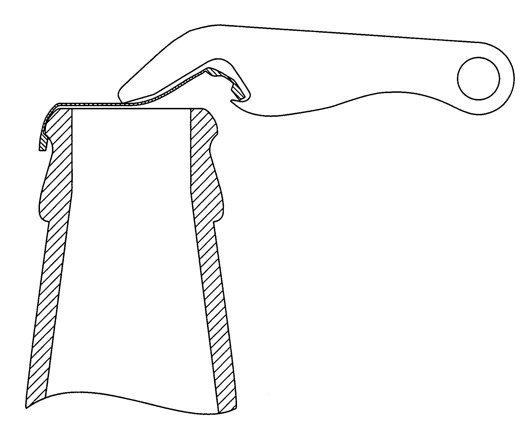
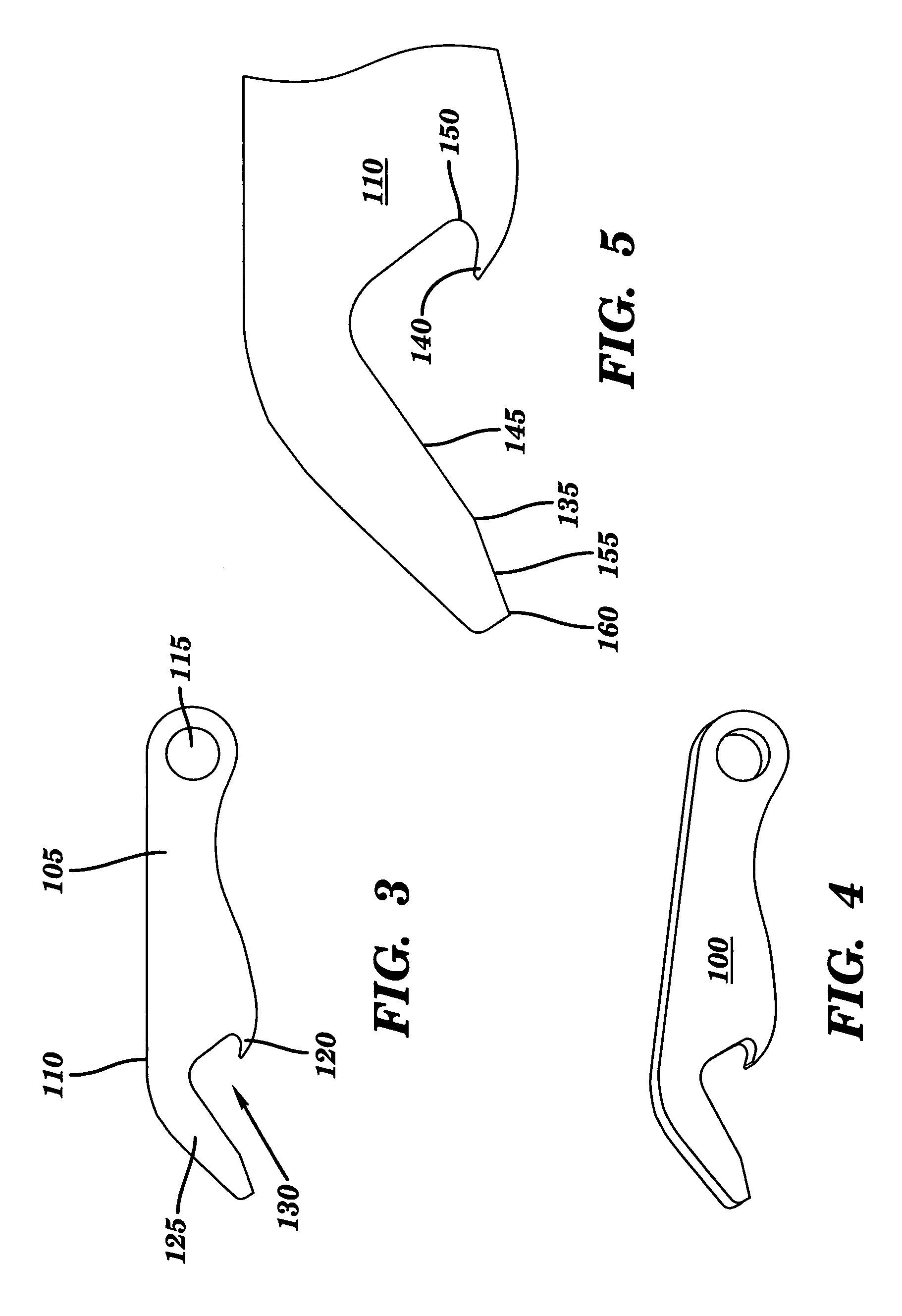
[0025]FIGS. 3–6 and 9–10 depict an improved bottle cap opener 100 according to the present invention. The opener 100 is shown in side view in FIGS. 3 and 9 and in isometric view in FIG. 4. An exploded view of a nose portion of the opener is shown in FIGS. 5 and 10. The opener 100 may be formed with a uniform thickness in the range of about 1.5–5.0 mm, (0.06–0.2 inches) but the preferred thickness is 2.3 mm, (0.09 inches). Ideally, the bottle cap opener 100 is formed from a metal having a hardness that is harder that the hardness of a conventional bottle cap so that the opener 100 will not be worn down by long term use. Accordingly, the opener 100 may be formed from a material having a Brinell Hardness above 200 to provide excellent wear resistant properties however, the opener 100 may also be formed of softer materials with a Brinell Hardness above 150 being acceptable.

[0026]Preferably the bottle cap opener 100 is formed from a corrosion resistant metal or from a metal that is surfa...


PUM


Abstract

A non slip bottle cap opener (100) for installing onto a key ring or key chain with other keys is formed with the approximate length and thickness of a standard key to allow it to be comfortably carried on the key ring or chain like an ordinary key. The opener includes a pry element (120) formed with a narrow leading edge (140) for installing within the annular gap (60) between the bottle cap and the bottle top. The pry element further includes an engaging surface (165) that acts upon an inside surface of the annular lip of the bottle cap to forcibly engaged with the annular lip to prevent the opener from slipping off of the bottle cap.

Description

BACKGROUND OR THE INVENTION[0001]1. Field of the Invention[0002]The invention relates to bottle cap removers or bottle openers and specifically provides a non-slip bottle cap remover for fitting compactly on a key ring with standard keys. In particular the portable bottle cap remover of the present invention provides pry handle and bottle cap removing nose section of thin cross-section for fitting between keys on a key ring as well as an overall length approximately equal to the length of standards keys. In addition, the nose portion includes a pry element that fits within a gap between a bottle top and a bottle cap and a fulcrum element shaped to vary a bottle cap removing pry force over its range of motion.[0003]2. Description of Related Art[0004]Portable bottle cap removing tools or bottle openers are widely known and used to remove malleable bottle caps from beverage bottles and the like. Malleable bottle caps, usually metal, are generally crimped or otherwise formed over the to...

Claims


Application Information

Patent Timeline
Patent Type & Authority Patents(United States)
IPC IPC(8): B67B7/16
CPCB67B7/16
Inventor OLEKSY, JOHN R.
Owner OLEKSY JOHN R
Why Eureka
Try Eureka