
Air intake manifold

a composite and air intake technology, applied in the direction of air intakes for fuel, combustion-air/fuel-air treatment, machines/engines, etc., can solve problems such as adversely affecting performance, and achieve the effect of reducing thickness and weight, and reducing the thickness and weigh

Inactive Publication Date: 2006-08-08
TEETER DARRIN BLAKE
View PDF19 Cites 38 Cited by
  • Summary
  • Abstract
  • Description
  • Claims
  • Application Information

AI Technical Summary

Benefits of technology

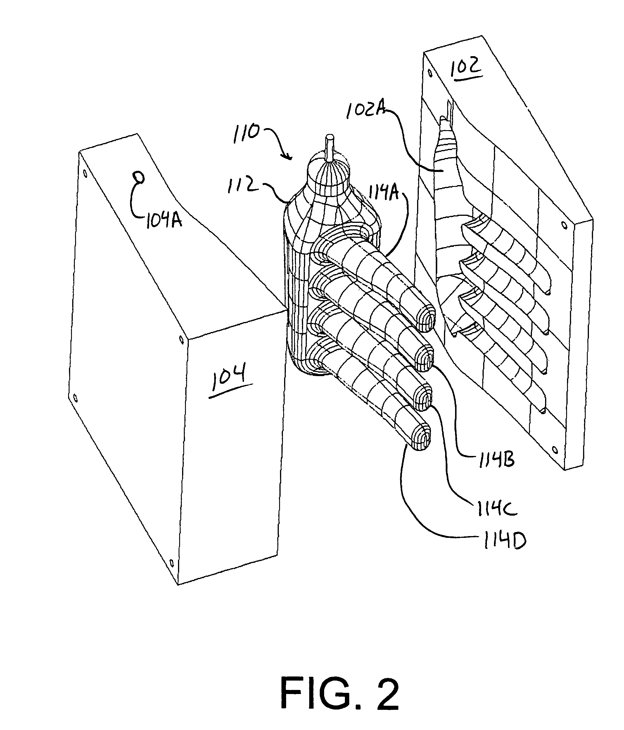
[0004]In an embodiment of the present invention the aforementioned need is addressed by providing a lightweight composite air intake manifold and a method for making such a manifold which allows the manifold designer to optimize the internal passage geometry for efficient air flow. A composite air intake manifold of the present invention includes a header and runners having communicating passages. The composite intake manifold is fashioned from resin impregnated carbon fiber cloth which is preferably impregnated and cured between a meltable core mold and a split outside mold. The carbon fiber cloth is oriented throughout the manifold to give the manifold maximum pressure resisting capability with minimum thickness and weight. Because virtually any shape may be adopted for the interior passages of the header and the runners, the interior passages of the header and runners may be shaped to enhance air flow through the manifold.

Problems solved by technology

Many prior art intake manifolds have been fashioned from cast aluminum which, for a typical four cylinder internal combustion engine, may weigh approximately 15 pounds and may act to heat the intake air charge, adversely affecting performance.

Method used


Image

  • Air intake manifold
  • Air intake manifold
  • Air intake manifold

Examples


Embodiment Construction

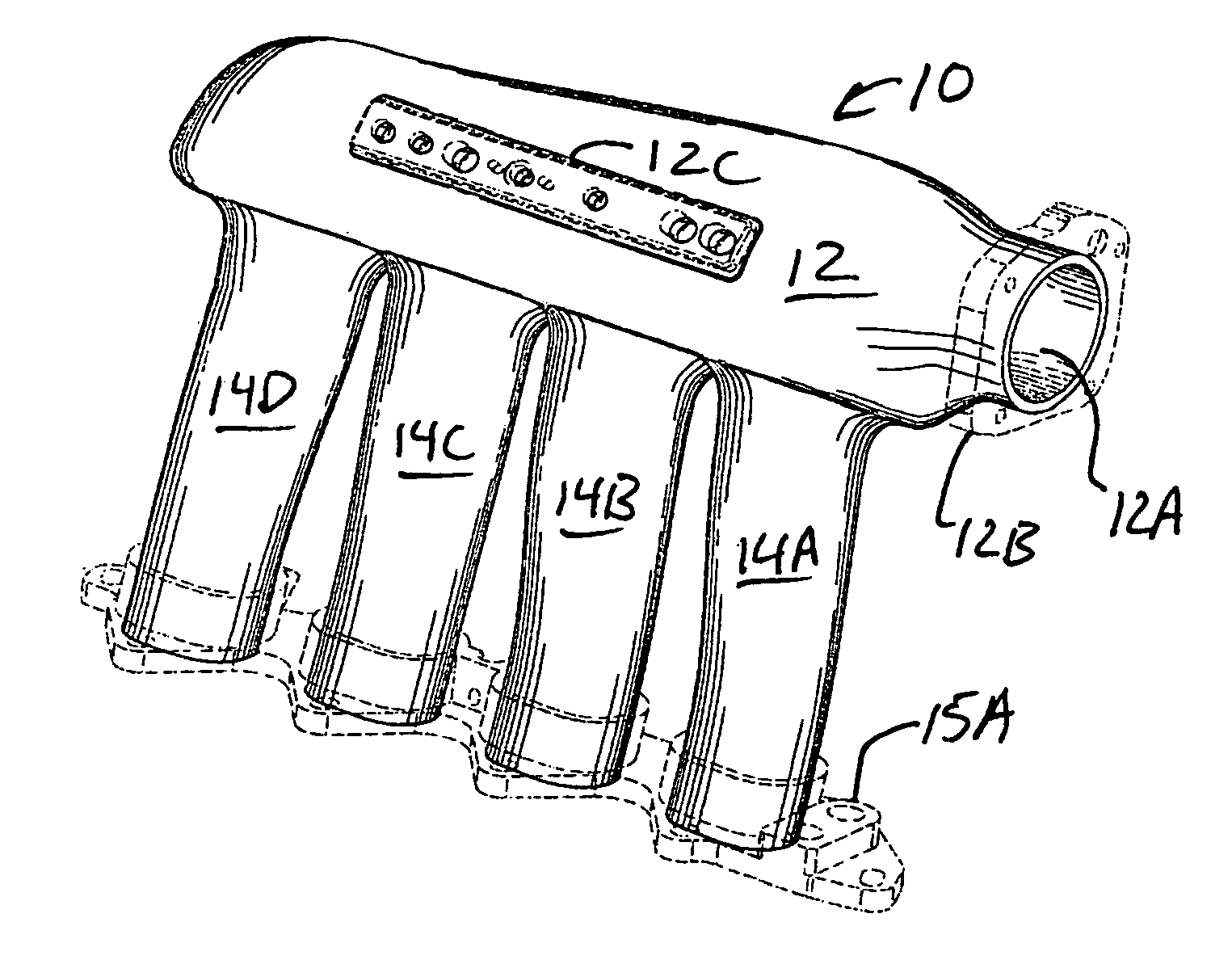
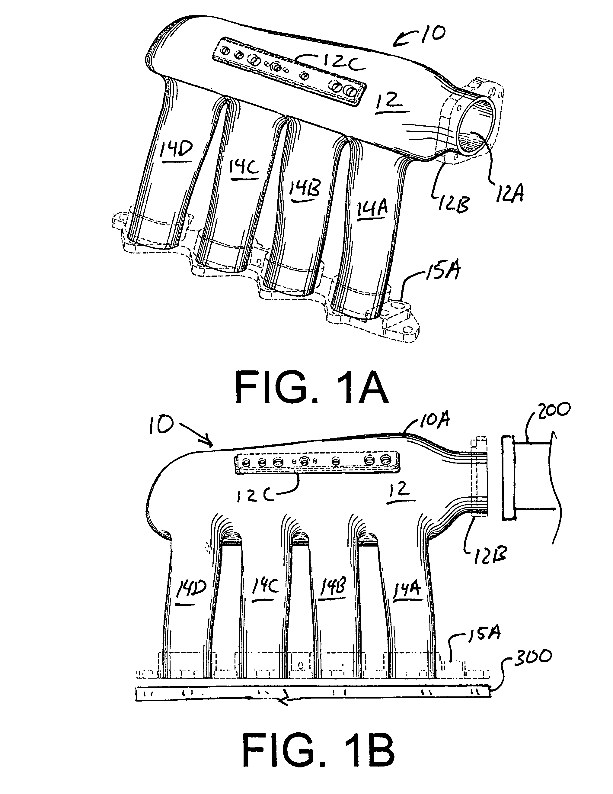
[0014]Referring to the drawings, FIGS. 1A and 1B illustrates a composite intake manifold 10. The composite intake manifold 10 includes a manifold body 10A which further includes a header 12 and, in this example, four runners 14A, 14B, 14C and 14D extending from the body of header 12. Each of runners 14A, 14B, 14C and 14D provides an outlet port. Runners 14A, 14B, 14C and 14D are bonded to an aluminum outlet fitting 15A for mating with the intake ports of the cylinders of an internal combustion engine 300 shown in FIG. 1B. Header 12 includes an inlet opening 12A around which is bonded an inlet fitting 12B for mating with the outlet fitting of an air supply 200 shown in FIG. 1B or other source of air. A second aluminum fitting 12C is also glued to header 12. Header 12 and runners 14A, 14B, 14C and 14D of intake manifold body 10A are integrally formed with resin impregnated high strength fabric. The method for fabricating intake manifold body 10A will be described in greater detail bel...


PUM

PropertyMeasurementUnit
temperaturesaaaaaaaaaa
temperatureaaaaaaaaaa

Abstract

A composite air intake manifold includes a header and runners having communicating passages. The composite intake manifold is fashioned from carbon fiber cloth which is preferably impregnated with resin and cured between a meltable core mold and a split outside mold. The carbon fiber cloth is oriented throughout the manifold to give the manifold maximum pressure resisting capability with minimum thickness and weight. Because virtually any shape may be adopted for the interior passages of the header and the runners, the interior passages of the header and runners may be shaped to enhance air flow through the manifold.

Description

CROSS REFERENCE TO RELATED APPLICATION[0001]This application claims the benefit of U.S. provisional application 60 / 553,927 filed Mar. 17, 2004.FIELD OF THE INVENTION[0002]This invention relates to a lightweight, composite air intake manifold for internal combustion engines and a method for making it.BACKGROUND OF THE INVENTION[0003]A need exists for lightweight intake manifolds for internal combustion engines capable of withstanding significant internal pressures. Many prior art intake manifolds have been fashioned from cast aluminum which, for a typical four cylinder internal combustion engine, may weigh approximately 15 pounds and may act to heat the intake air charge, adversely affecting performance. Moreover, there is a need for internal combustion engine intake manifolds having internal passages shaped and sized for efficient air flow. What is needed is a lightweight, high strength, low thermal mass intake manifold having internal passage geometry adapted to facilitate air flow...

Claims


Application Information

Patent Timeline
Patent Type & Authority Patents(United States)
IPC IPC(8): F02M35/104
CPCF02M35/10347F02M35/10321F02M35/10334F02M35/10098F02M35/10052F02M35/10072
Inventor TEETER, DARRIN BLAKE
Owner TEETER DARRIN BLAKE
Learn More