Heat radiating fin assembly and thermal module formed therefrom

a technology of heat radiating fins and thermal modules, which is applied in the direction of electrical apparatus construction details, indirect heat exchangers, lighting and heating apparatus, etc., can solve the problems of slow running of the cpu, increased heat produced and accumulated in the computer, and computer being subject to the danger of shutdown or even serious damage, so as to reduce the drop in airflow and flow resistance, shortened airflow paths, and improved airflow inlet.

Active Publication Date: 2010-05-20
BEIJING AVC TECH RES CENT
View PDF13 Cites 0 Cited by
  • Summary
  • Abstract
  • Description
  • Claims
  • Application Information

AI Technical Summary

Benefits of technology

[0011]With the airflow guiding section, the heat radiating fin assembly and the thermal module of the present invention can have widened airflow inlets, shortened airflow paths, reduced airflow pressure drop and flowing resistance, and upgraded cooling air flowing efficiency, and can therefore provide excellent heat dissipating effect.
[0012]In brief, the present invention provides at least the following advantages: (1) having good heat dissipating efficiency; (2) enabling reduced cooling airflow pressure drop; (3) having high heat-exchange efficiency; (4) having simple structure; (5) preventing heat from stagnating around the heat radiating fin assembly; (6) allowing heat source to quickly diffuse into ambient environment; and (7) enabling upgraded cooling air flowing efficiency.

Problems solved by technology

The CPU would become slow in running when the heat produced and accumulated in the computer gradually increases.
When the heat accumulated in the computer exceeds an allowable limit, the computer is subject to the danger of shutdown or even becoming seriously damaged.
As a result, the cooling airflows flowing through the heat dissipating spaces 112 are subject to increased pressure drop and slowed flowing speed, which have adverse influences on the heat dissipating efficiency of the thermal module.
In brief, the conventional heat radiating fin assembly and the thermal module formed therefrom have the following disadvantages: (1) providing only very narrow heat dissipating spaces; (2) having poor heat-exchange efficiency; (3) providing only low heat dissipating efficiency; (4) having quiet long cooling airflow paths; and (5) subjecting the cooling airflow to increased pressure drop.

Method used


Image

  • Heat radiating fin assembly and thermal module formed therefrom
  • Heat radiating fin assembly and thermal module formed therefrom
  • Heat radiating fin assembly and thermal module formed therefrom

Examples


Embodiment Construction

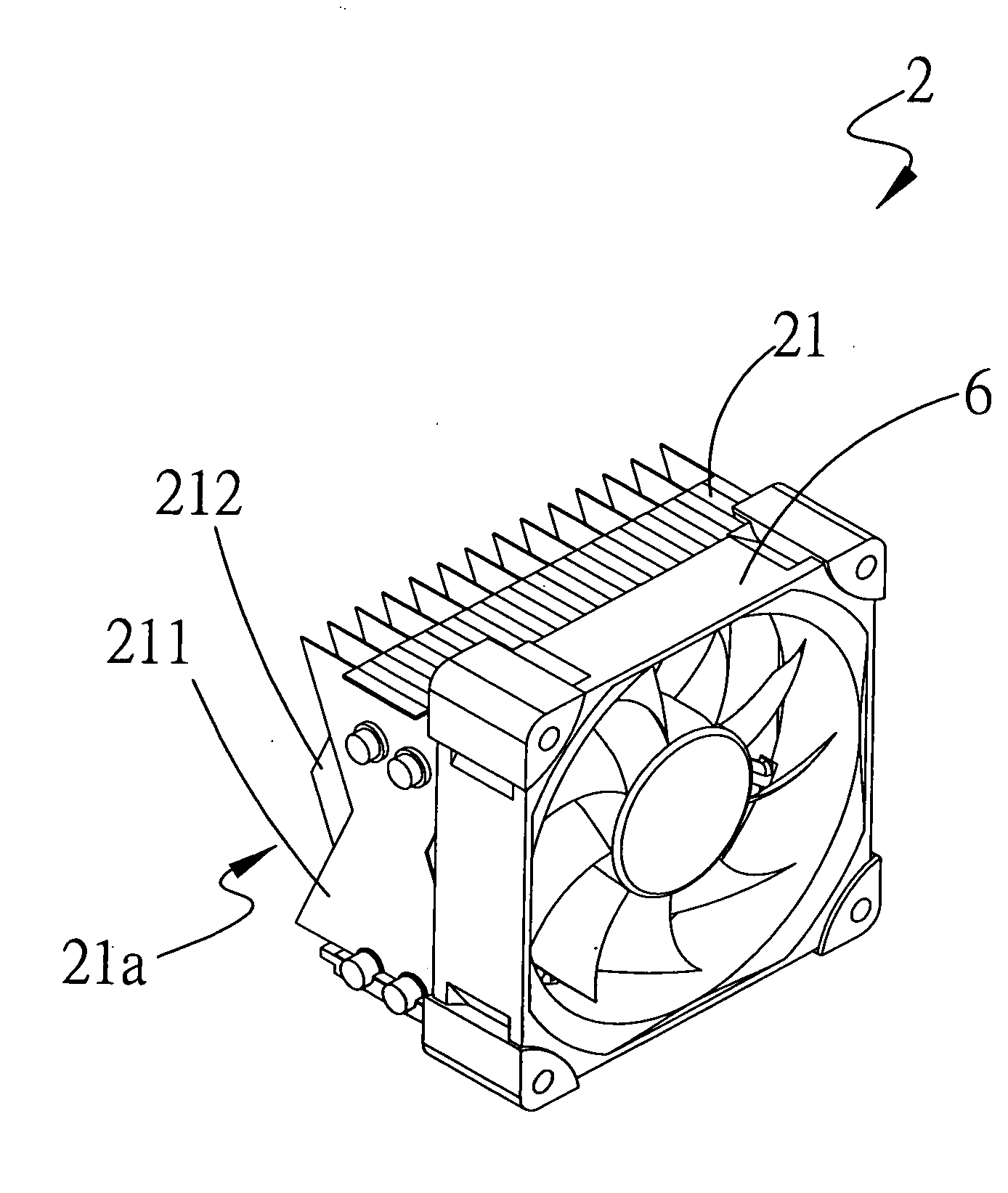
[0025]Please refer to FIGS. 2 and 3A, which are partially exploded and fully assembled perspective views, respectively, of a heat radiating fin assembly 21 according to a first preferred embodiment of the present invention. As shown, the heat radiating fin assembly 21 includes a plurality of sequentially stacked first heat radiating fins 212 and second heat radiating fins 211. The first and the second heat radiating fins 212, 211 are alternately arranged in the heat radiating fin assembly 21. Each of the first heat radiating fins 212 has an outward projected point 2123 formed on at least one lateral side thereof, and each of the second heat radiating fins 211 has an inward receded point 2113 formed on at least one lateral side corresponding to the lateral side of the first heat radiating fin 212 having the projected point 2123 formed thereon, such that the lateral sides of the first and the second heat radiating fins 212, 211 having the projected points 2123 and the receded points 2...


PUM


Abstract

A heat radiating fin assembly is formed from alternately stacked first and second heat radiating fins. The first and the second heat radiating fins each are provided on at least one lateral side with a projected point and a receded point, respectively, to thereby define an airflow guiding section on at least one longitudinal side of the heat radiating fin assembly. The airflow guiding section includes a first and a second airflow inlet, and a middle airflow inlet located between the first and the second airflow inlet. The heat radiating fin assembly can be associated with at least one heat pipe and a base to form a thermal module. The airflow guiding section enables widened airflow inlets, shortened airflow paths, reduced airflow pressure drop and flowing resistance, and upgraded cooling air flowing efficiency, so that the heat radiating fin assembly and the thermal module can provide excellent heat dissipating effect.

Description

FIELD OF THE INVENTION[0001]The present invention relates to a heat radiating fin assembly and a thermal module formed therefrom, and more particularly, to a heat radiating fin assembly and a thermal module formed therefrom capable of reducing cooling airflow pressure drop.BACKGROUND OF THE INVENTION[0002]With the progress in the technological fields, all kinds of electronic elements have constantly upgraded operating ability, which also brings increased heat produced by the electronic elements during the operation thereof. Therefore, people demand more and more for heat sinks with improved performance. For the purpose of providing enhanced heat dissipating function, most of the conventional heat sinks will adopt a heat radiating fin assembly consisting of a plurality of sequentially stacked heat radiating fins. Researches have been constantly conducted to develop improved heat radiating fins, and a high-performance heat sink has become one of the most important targets in the indus...

Claims


Application Information

Patent Timeline
Patent Type & Authority Applications(United States)
IPC IPC(8): H05K7/20
CPCH01L23/3672H01L23/427H01L23/467H01L2924/0002H01L2924/00
Inventor LIN, SHENG-HUANG
Owner BEIJING AVC TECH RES CENT
Why Eureka
Try Eureka