
Receptacle for accommodating at least one pencil

a technology for storing containers and pencils, applied in the direction of containers, rigid containers, applications, etc., can solve the problems of not being attractive from aesthetic points of view, injury risk,

Inactive Publication Date: 2006-08-08
SCHWAN STABILO SCHWANHAUSSER GMBH & CO
View PDF12 Cites 3 Cited by
  • Summary
  • Abstract
  • Description
  • Claims
  • Application Information

AI Technical Summary

Benefits of technology

[0005]In other words in accordance with the invention there are provided two matters for attaining the specified object: on the one hand an edge which is at the free end of the end portion of the first connecting portion is arranged within the internal space of the receptacle. As a result, at least when the receptacle is closed, the edge does not interfere either with handling or the aesthetic effect. Any risk of injury is also eliminated, when the container is closed. Secondly however it is also provided in accordance with the invention that the free end of said end portion or the edge does not project for example into the internal space but is bent over on to the second wall element. The consequence of that arrangement of the edge is that the edge cannot cause any interference in any fashion. More specifically, as it is towards the adjacent wall element, it does not adversely affect handling of the receptacle, for example when removing a pencil. In addition, alignment of the edge with the adjacent wall element excludes a risk of injury because a user cannot come into contact with the edge at all. Finally, the fact that the edge is ‘concealed’ provides an improvement in the aesthetic aspect.
[0016]In that respect, for the purposes of assembly of the receptacle, the two wall elements are ‘folded’ towards each other. Overall, that makes it possible to achieve a minimisation in respect of connecting devices because in fact the two wall elements are already connected together on one side.
[0023]In other words, in accordance with this configuration of the invention, in particular a stamped or cut edge forming a particularly high risk of injury is ‘concealed’ by bending over towards the adjacent wall element, thereby achieving the advantages described hereinbefore.
[0026]In order to impart stability to the receptacle, a particularly preferred embodiment of the invention provides at least one stiffening rib which is further preferably in the shape of a bay configuration. Such a bay configuration is more specifically particularly easy to produce in particular in the context of a deep drawing process. In contrast to the provision of a stiffening rib by a corresponding increase in wall thickness, the design afforded by a bay configuration also saves on material.
[0029]In other words the invention—as also in the other configurations—even in the case of a design configuration with a partition, provides a one-piece ‘cutting pattern’ from which a three-dimensional receptacle is afforded by a procedure involving bending over or folding and connecting of connecting portions. In particular in that way it is possible to automate the manufacturing process.

Problems solved by technology

As the edges are sometimes comparatively sharp, they cause problems when handling the receptacle and even involve a risk of injury.
In addition they are not very attractive from aesthetic points of view.

Method used


Image

  • Receptacle for accommodating at least one pencil
  • Receptacle for accommodating at least one pencil
  • Receptacle for accommodating at least one pencil

Examples


Embodiment Construction

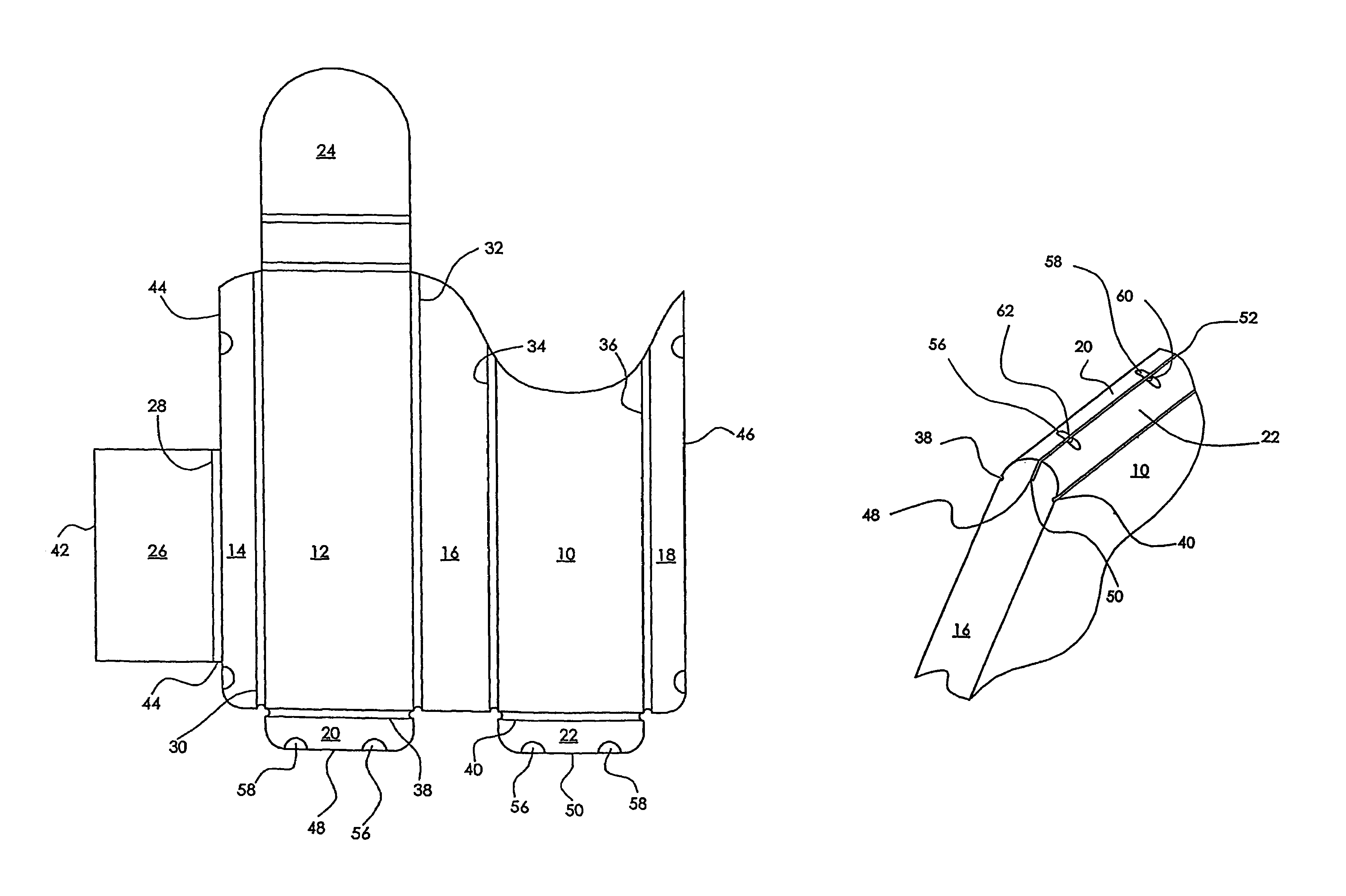
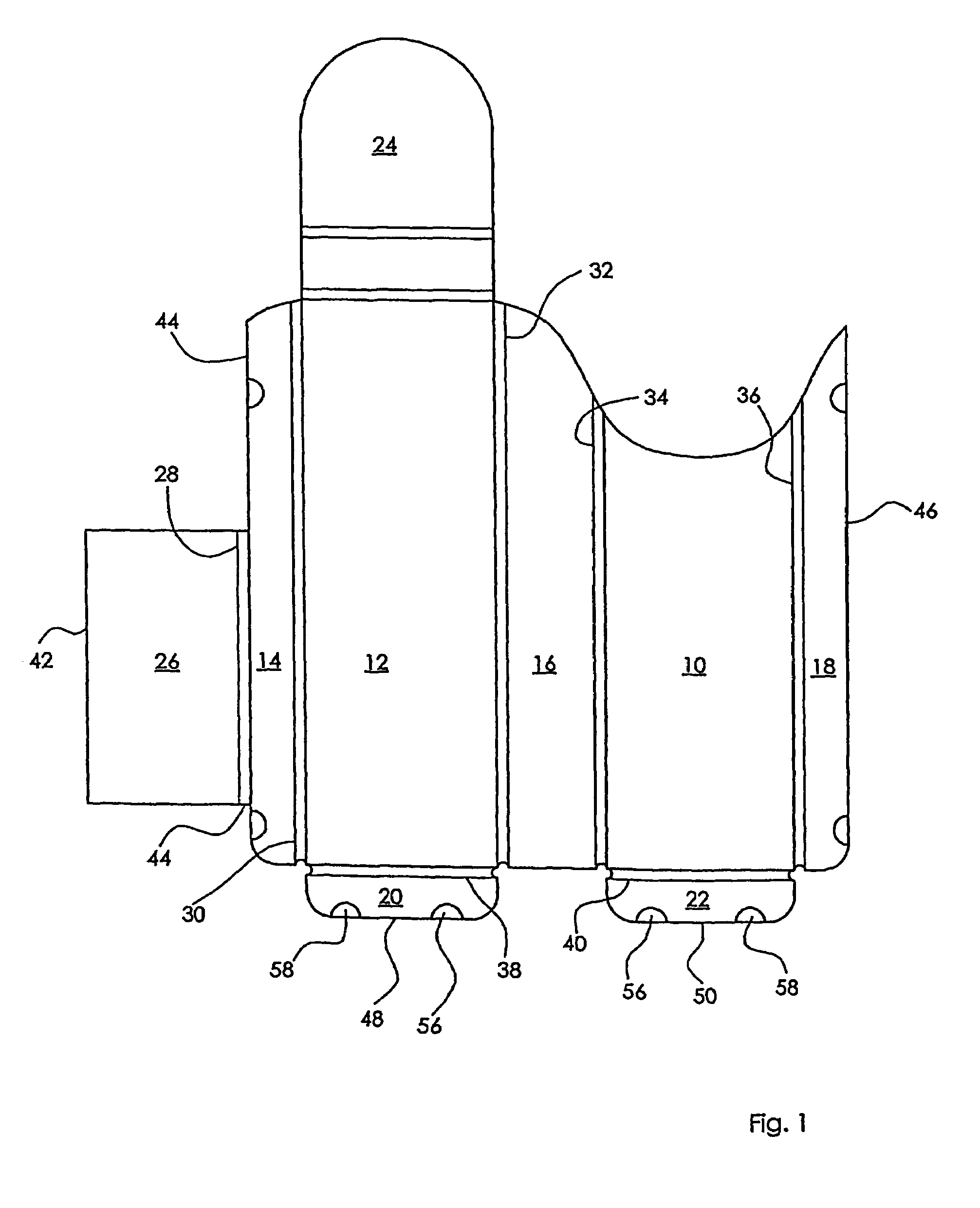
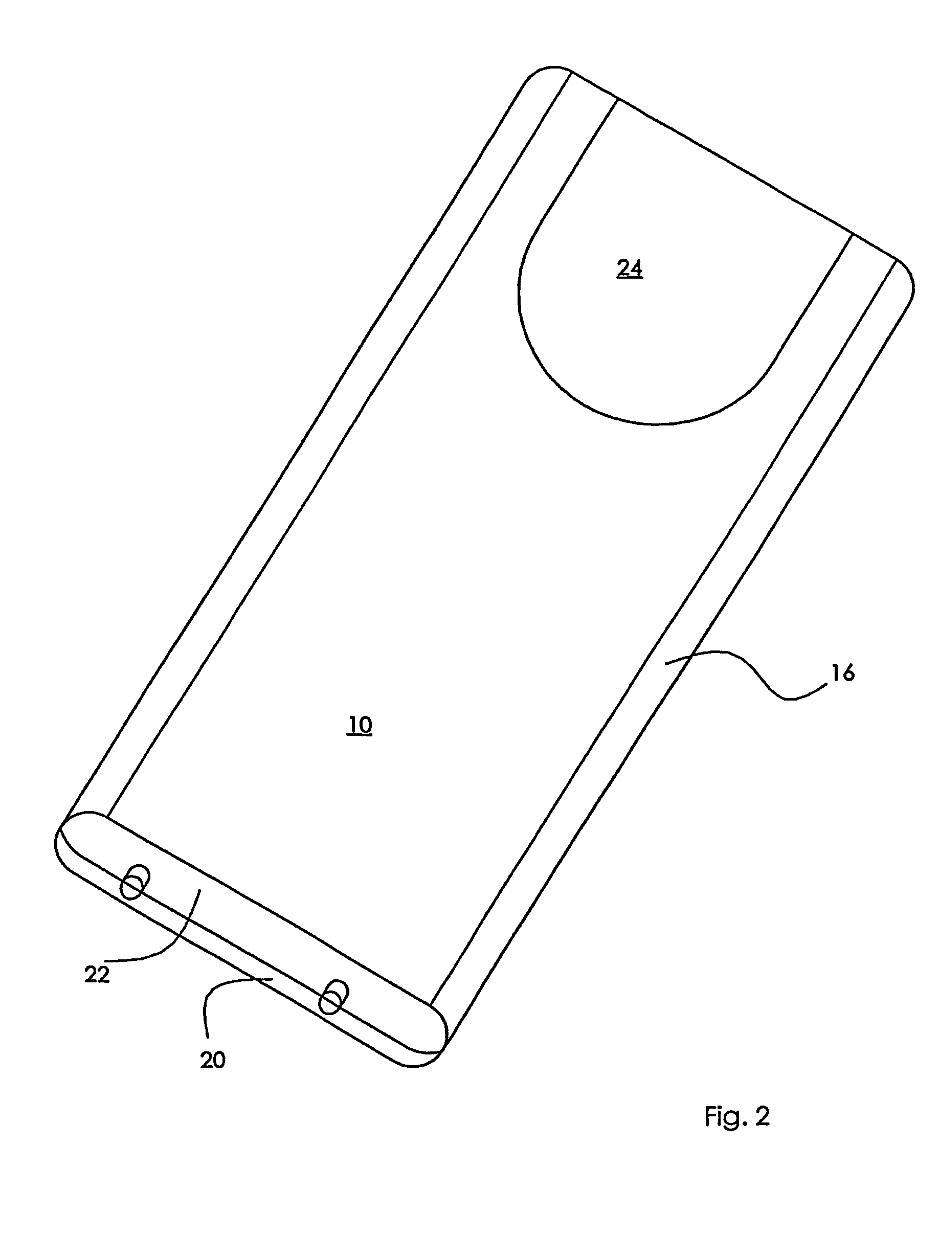
[0037]In accordance with the development, shown in FIG. 1, of the receptacle in accordance with a particularly preferred embodiment of the invention, the following elements are provided:[0038]a front wall 10, a rear wall 12, side elements 14, 16, 18, 20 and 22, a closure flap 24 and an intermediate partition 26.

[0039]The above-specified elements are all formed in one piece with each other, more specifically by deep drawing a PET foil or sheet of a wall thickness of 250 μm. Provided between the specified individual elements are respective bending hinges 28, 30, 32, 34, 36, 38 and 40, whereby ‘folding’ to assemble the receptacle as shown in FIG. 2 is simplified. The bending hinges are each in the shape of a bay configuration produced in the course of the deep drawing operation, as is shown in section in FIG. 3.

[0040]After the deep drawing operation which is performed on webs of foil, the individual receptacle cutting patterns are separated from the respectively preceding and following...


PUM

PropertyMeasurementUnit
thicknessaaaaaaaaaa
thicknessaaaaaaaaaa
widthaaaaaaaaaa

Abstract

A receptacle for accommodating at least one pencil, comprising an inner space and a first wall element that delimits the inner space. The first wall element has a first connecting section that is located inside the inner space, and at the free end of this connecting section, an end section is to be folded back onto a second element that is adjacent to the first connecting section.

Description

BACKGROUND OF THE INVENTION[0001]The invention concerns a receptacle for accommodating at least one pencil, comprising an internal space and a first wall element forming a boundary of the internal space.[0002]Receptacles of the above-indicated kind are known. They generally have peripherally extending edges of at least two millimeters in width, along which individual parts of the receptacle are welded, the individual parts usually involving a cover and a bottom. As the edges are sometimes comparatively sharp, they cause problems when handling the receptacle and even involve a risk of injury. In addition they are not very attractive from aesthetic points of view.[0003]The object of the invention is to develop the receptacle of the kind set forth in the opening part of this specification, in such a way that handling of the receptacle is improved, any risk of injury is eliminated and the receptacle is aesthetically attractive.SUMMARY OF THE INVENTION[0004]According to the invention the...

Claims


Application Information

Patent Timeline
Patent Type & Authority Patents(United States)
IPC IPC(8): A45C11/34B43K23/00B65D85/28
CPCA45C11/34B65D85/28B43K23/001
Inventor MOCK, GERHARD
Owner SCHWAN STABILO SCHWANHAUSSER GMBH & CO
Learn More