Tool vending machine and method therefore

a vending machine and tool technology, applied in the field of vending machines, can solve the problems of inherently expensive, inability to return tools, and inability to charge the machinist for the cost of that particular tool,

Active Publication Date: 2006-08-08
AUTOCRIB
View PDF7 Cites 51 Cited by
  • Summary
  • Abstract
  • Description
  • Claims
  • Application Information

AI Technical Summary

Problems solved by technology

The problem with this type of arrangement is that the tool never gets back to the supply room and actually the ends up probably going home with the machinist to stockpile the machinist's home tool supply.
That employee is required to sign out the tool to the machinist, and if the machinist does not bring back the tool to the tool crib, then the expense of that particular tool will then be charged to the machinist.
The problem with the tool crib is that it has to be manned by an employee and therefor is inherently expensive.
If the tool is not returned, then the expense of the tool can then be charged to the machinist.
However, there is one significant deficiency of the tool vending machine that has been previously constructed.
That deficiency is that there is no consideration being given to the size of the tool that is being dispensed.
This, of course, is not desirable.

Method used


Image

  • Tool vending machine and method therefore
  • Tool vending machine and method therefore
  • Tool vending machine and method therefore

Examples


Embodiment Construction

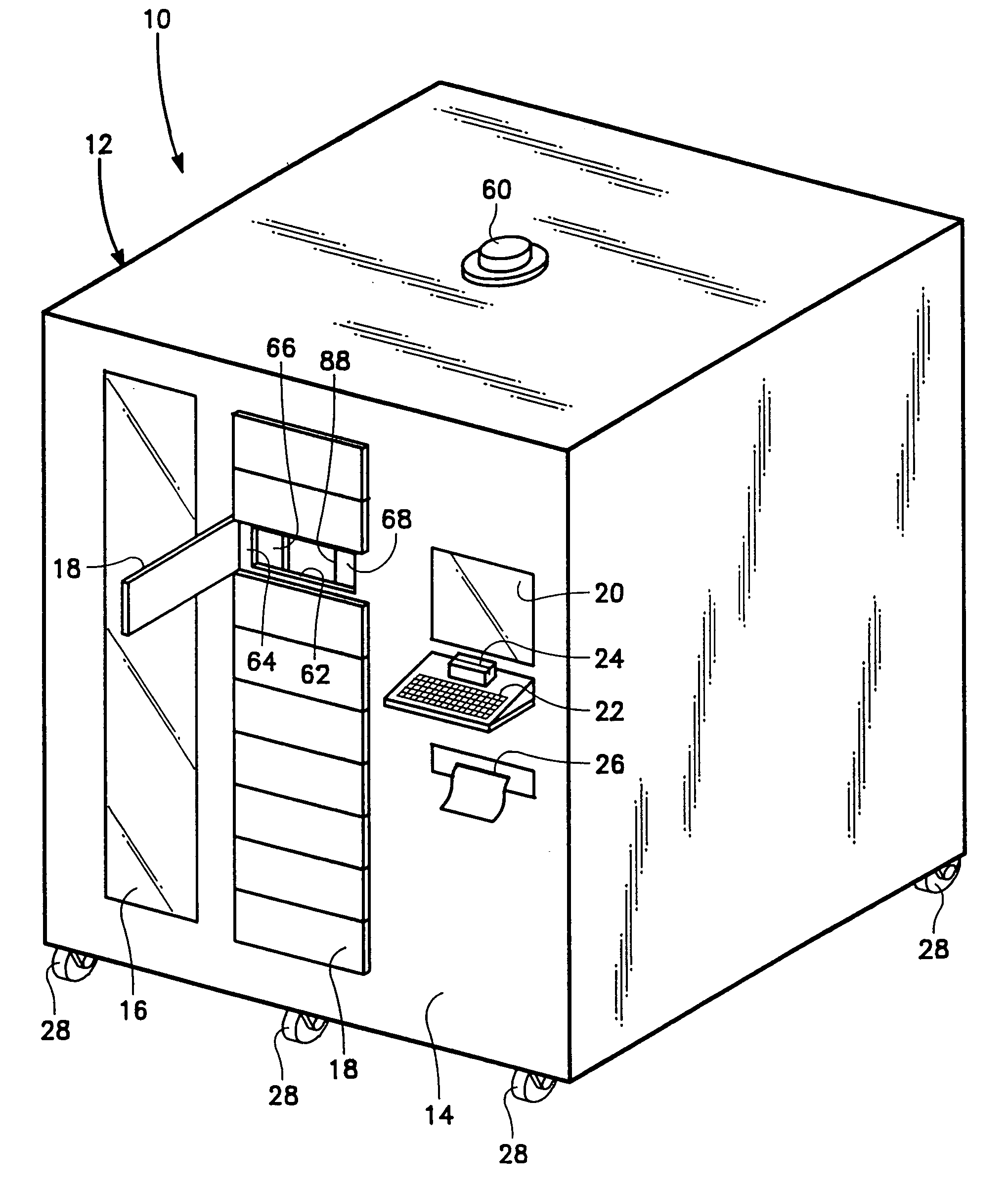
[0036]The present invention is utilized in conjunction with a rotary carousel-style storage and retrieval parts bin inventory machine which is basically disclosed within U.S. Pat. No. 5,337,920. Typically, this type of machine will have several different levels of carousels, usually fifteen levels. This type of vending machine is in common use as an automated vending machine for industrial users to dispense tools. The machine of this patent provides authorized users secure access to a requested tool by way of a touch screen computer interface. There is controlling computer software that validates the user's request against a preset security and stock level parameters, and once the user is approved, the carousel controller rotates the carousel to locate a compartment of the bin carousel directly adjacent an openable door of the inventory machine.

[0037]Referring particularly to FIG. 1, there is shown vending machine 10 of this invention which includes a box-like metal sheet material h...


PUM


Abstract

A tool vending machine which permits human access to only a single size compartment of a plurality of different sized compartments at a time so that the user is only able to extract a tool that is contained within that single compartment and does not permit access to any other compartment. The particular compartment is to be manually selected by the human user.

Description

BACKGROUND OF THE INVENTION[0001]1. Field of the Invention[0002]The field of this invention relates to a vending machine and more particularly to a vending machine which is designed to dispense tools.[0003]2. Description of the Related Art[0004]Manufacturers commonly employ machinists. These machinists use tools. Typical tools will be drill bits, saw blades, socket drivers, chisels and the like. There are literally hundreds of different tools that are commonly used by machinists in manufacturing facilities.[0005]In the past, it has been common for these machinists to go to a supply room for such tools and select whatever tool that they wanted and then go ahead and use the tool accordingly. The problem with this type of arrangement is that the tool never gets back to the supply room and actually the ends up probably going home with the machinist to stockpile the machinist's home tool supply.[0006]It has been common within manufacturing plants to overcome this problem by establishing ...

Claims


Application Information

Patent Timeline
Patent Type & Authority Patents(United States)
IPC IPC(8): G07F11/00
CPCG07F17/0042G07F11/62
Inventor PIXLEY, STEPHEN M.SCHURTER, CHARLES J.MCMAHON, JAMES J.
Owner AUTOCRIB
Why Eureka
Try Eureka