Side air bag device

a technology of airbags and side airbags, which is applied in the direction of pedestrian/occupant safety arrangements, vehicular safety arrangments, vehicle components, etc., to achieve the effect of inhibiting the backflow of gas and minimizing the number of inflators

Inactive Publication Date: 2006-08-08
HONDA MOTOR CO LTD
View PDF19 Cites 63 Cited by
  • Summary
  • Abstract
  • Description
  • Claims
  • Application Information

AI Technical Summary

Benefits of technology

[0010]With the above arrangement, the gas generated by the single inflator is diverted by a branching pipe and supplied to the plurality of air bags, and hence the plurality of air bags can be deployed while minimizing the number of the inflator.
[0011]...

Problems solved by technology

On the other hand, the side air bag device described in U.S. Pat. No. 6,349,964 has the following problem: a difference in internal pressure is generated by setting different open areas of openings thr...

Method used


Image

  • Side air bag device
  • Side air bag device
  • Side air bag device

Examples


first embodiment

[0035]the present invention will now be described with reference to FIGS. 1 to 4B.

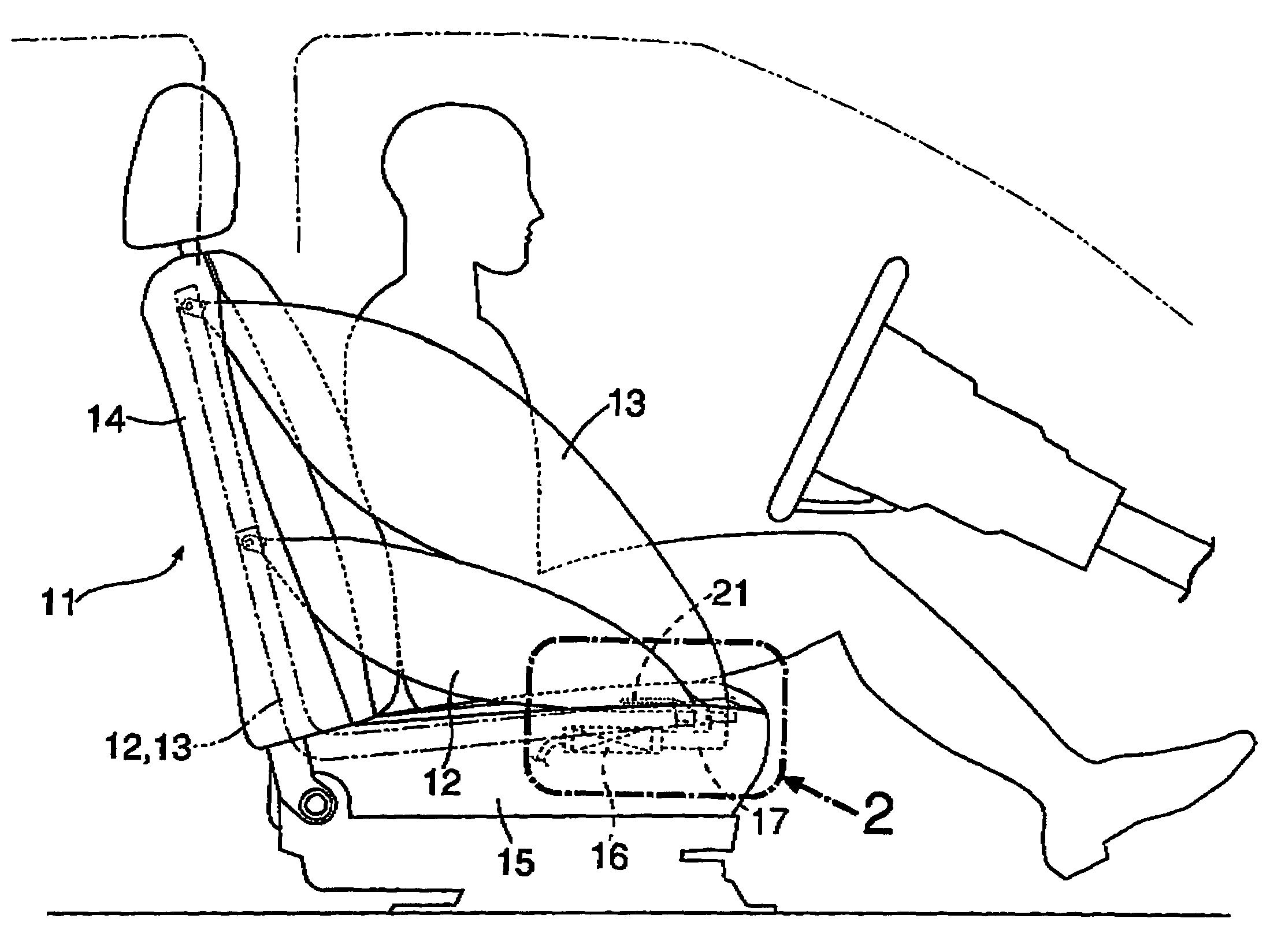
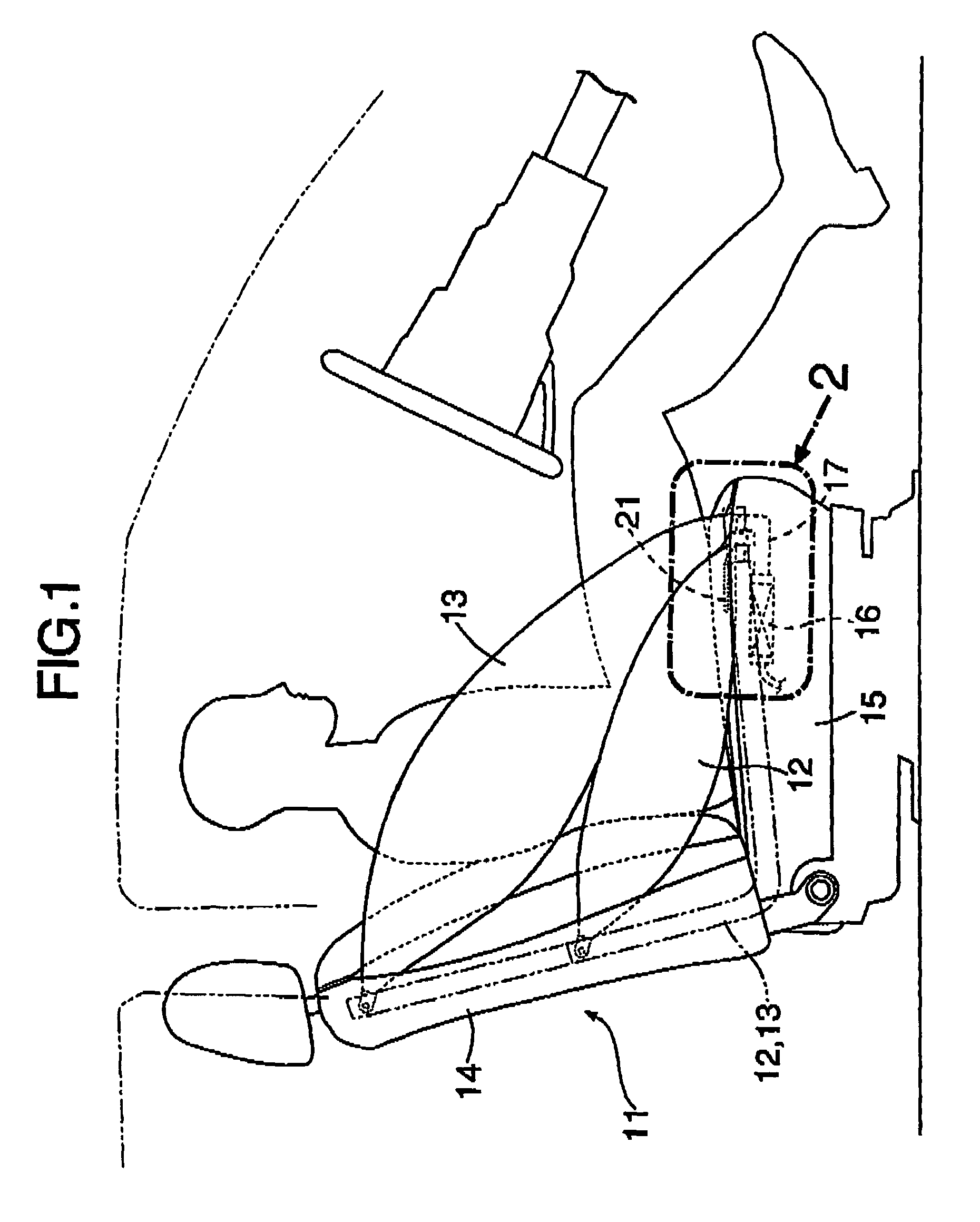
[0036]As shown in FIG. 1, a side air bag device is disposed in a right side of a front seat 11 of an automobile, namely, in a side opposed to a front door and a center pillar, and includes a first air bag 12 and a second air bag 13. The first air bag 12 is deployed so that it extends to connect a vertically central portion of the seat back 14 to a front end of a seat cushion 15, and protects a side of a waist of an occupant. The second air bag 13 is deployed so that it extends to connect an upper end of a seat back 14 to the front end of the seat cushion 15, and protects a side of a breast of the occupant. The first and second air bags 12 and 13 in folded states before deployment are embedded in the right sides of the seat back 14 and the seat cushion 15, as shown by dashed lines, and are each deployed in such a manner that it breaks a sewn portion of a skin of the front seat 11 by a pressure of expans...


PUM


Abstract

A gas generated by an inflator is supplied through a branching pipe to first and second air bags, which are deployed from a side of a seat to a space between an inner surface of a side of a vehicle compartment and an occupant. A one-way valve mounted in the branching pipe permits the gas to move from the second air bag to the first air bag and inhibits a back flow of the gas, whereby the internal pressure in the first air bag can be maintained higher than that in the second air bag, to thereby restrain the occupant's waist more strongly than the occupant's breast. Moreover, the gas generated by the single inflator is diverted by the branching pipe and supplied to the two air bags. Therefore, the two air bags can be deployed while minimizing the number of the inflator.

Description

BACKGROUND OF THE INVENTION[0001]1. Field of the Invention[0002]The present invention relates to a side air bag device comprising a plurality of air bags which are accommodated in folded states in a side of a seat for an occupant and which are expanded by a gas generated by an inflator upon side collision of a vehicle to be deployed between an inner surface of a side of a vehicle compartment and the occupant.[0003]2. Description of the Related Art[0004]A conventional side air bag devices is known, for example, from U.S Pat. No. 5,464,246 and U.S. Pat. No. 6,349,964. An air bag in the side air bag device described in U.S Pat. No. 5,464,246 is formed into a cylindrical shape and adapted to be deployed to connect an upper end of a seat back and a front end of a seat cushion, thereby restraining an occupant's body from a side of the breast to a side of the waist. An air bag in the side air bag device described in U.S Pat. No. 6,349,964 is divided into upper and lower chambers so that an...

Claims


Application Information

Patent Timeline
IPC IPC(8): B60R21/207B60R21/26B60R21/16B60R21/233B60R21/20B60R21/2346B60R21/261
CPCB60R21/207B60R21/23138B60R21/23184B60R21/2346B60R2021/2615B60R2021/23107B60R2021/26094
Inventor HONDA, TAKASHI
Owner HONDA MOTOR CO LTD
Why Eureka
Try Eureka