Underride protection bumper for a trailer

a technology for trailers and bumpers, applied in bumpers, vehicle components, pedestrian/occupant safety arrangements, etc., can solve the problems of damage to the underriding vehicle and injury to the occupants therein, and achieve the effect of prolonging the ride down of the impacting vehicl

Inactive Publication Date: 2006-08-08
GOERTZ ALAN R
View PDF8 Cites 62 Cited by
  • Summary
  • Abstract
  • Description
  • Claims
  • Application Information

AI Technical Summary

Benefits of technology

[0004]An underride protection bumper for a trailer of novel design is provided which effectively functions as two separate energy-absorbing bumpers at different stages of an impact, allowing an optimal combination of energy absorption capability, underride prevention and extended ride-down of the impacting vehicle.
[0006]The design of the underride protection bumper permits the impact member to cause the impacting vehicle to dissipate energy through deformation to the impacting vehicle. The impacting energy is also transferred to the proximal portions, which at some level of impact energy will plastically deform, pivoting away from the impact such that the distal portions are moved inboard of the proximal portions. The impact member maintains contact with the impacting vehicle throughout the pivoting motion. Once pivoting of the proximal portions is complete (which may be when the proximal portions abut the underside of the trailer), the distal portions are able to continue absorbing impact energy, allowing for a longer ride-down period for the impacting vehicle and minimizing further underride.
[0007]In one aspect of the invention, a brace member may be connected between the trailer attachment members. The brace member provides additional stability to the distal and proximate portions. The brace member may include a pair of cross member supports arranged in an X-shape connected between the distal portions, preferably in generally the same plane as the impact member. The X-shaped brace member prevents substantial lateral movement of the distal portions relative to the proximal portions.
[0009]In another aspect of the invention, a supplemental impact member may be slidably adjustably positioned within the impact member to telescopically extend therefrom, thus effectively increasing the potential contact with an impacting vehicle. The supplemental impact member may be especially useful when the bumper is mounted to the trailer transversely, to absorb a side impact. In that instance, the supplemental impact member may extend to fill a gap between the impact member and the trailer wheels.
[0013]Another embodiment of an underride protection bumper includes first and second substantially parallel, elongated trailer attachment members having vertical arms spaced apart from one another with an impact member spanning therebetween. Diagonal support members extend diagonally inboard from trailer structure, a buck plate, or other supportive structure, to the trailer attachment members. The diagonal supports are preferably portions of a continuous cable threaded through eyelets formed in the trailer structure or other support structure and in the trailer attachment members. An impacting vehicle directing an inboard force on the impact member will cause the diagonal supports to pull outboard in tension on the trailer attachment members, thus strengthening the bumper, which helps to slow and minimize underride of the vehicle and may transfer some of the impact energy through additional deformation to the trailer structure, buck plate or other supportive structure as well as from one of the trailer attachment members to the other trailer attachment member.
[0014]Still another embodiment of an underride protection bumper includes trailer structure, such as bogey slider rails and a pair of substantially parallel elongated trailer attachment members each having a proximal portion connected to the trailer structure. An impact member spans between the proximal portions such that it is presented for energy-absorbing contact with an impacting vehicle. A support member extends diagonally inboard between the trailer attachment members and the trailer structure. An inboard-directed force upon the impact member places the support member in tension to strengthen the bumper.

Problems solved by technology

This presents a risk that a passenger vehicle will underride the trailer in an accident, potentially resulting in damage to the underriding vehicle and injury to occupants therein.

Method used


Image

  • Underride protection bumper for a trailer
  • Underride protection bumper for a trailer
  • Underride protection bumper for a trailer

Examples


Embodiment Construction

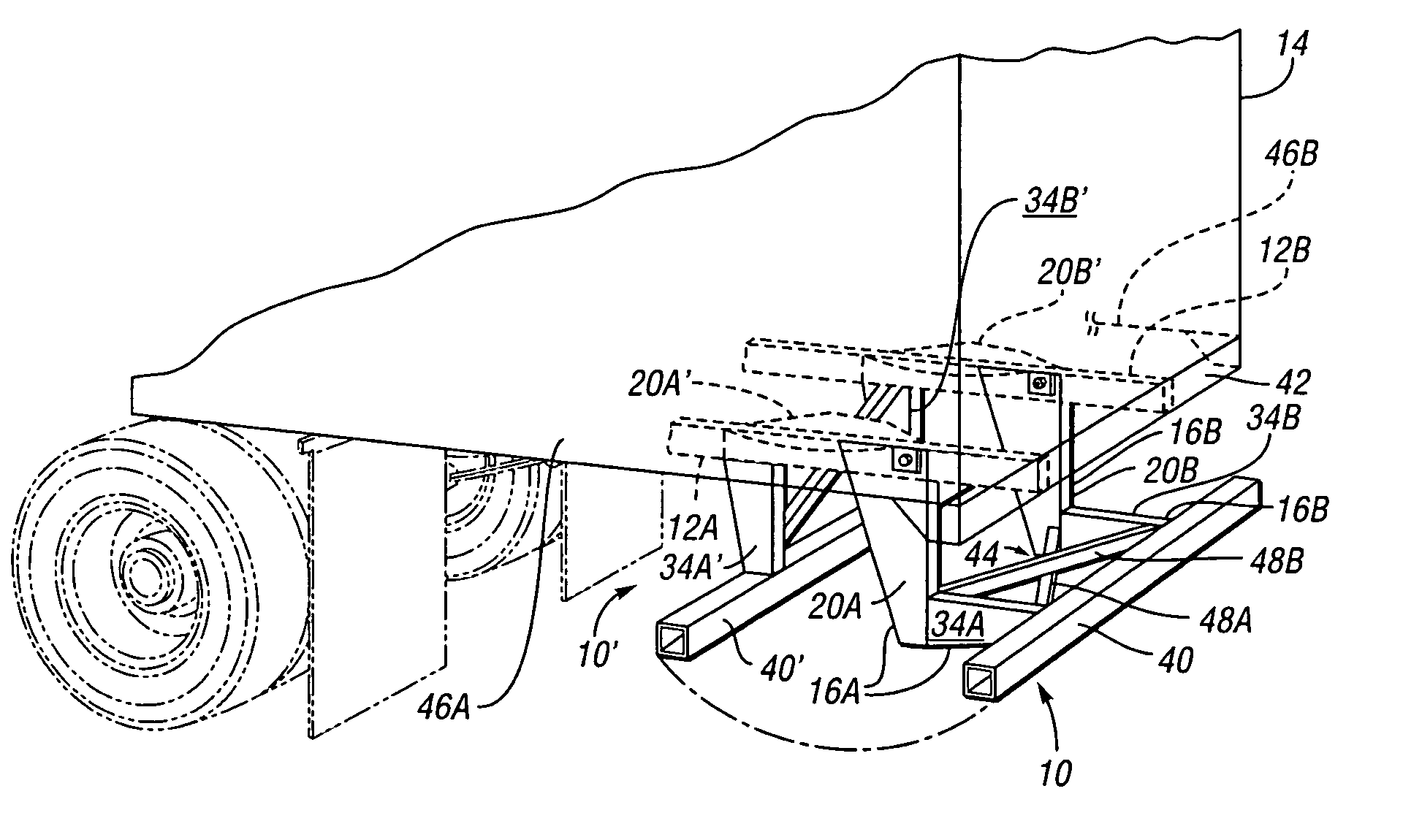
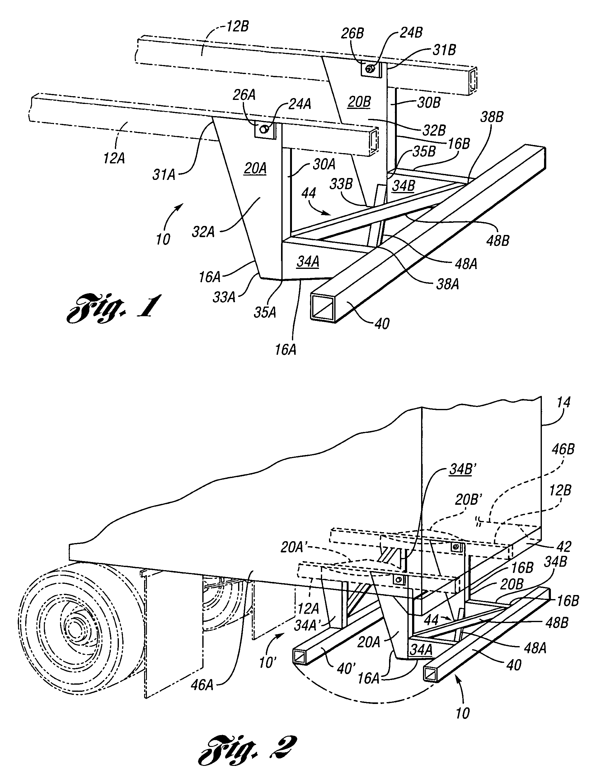
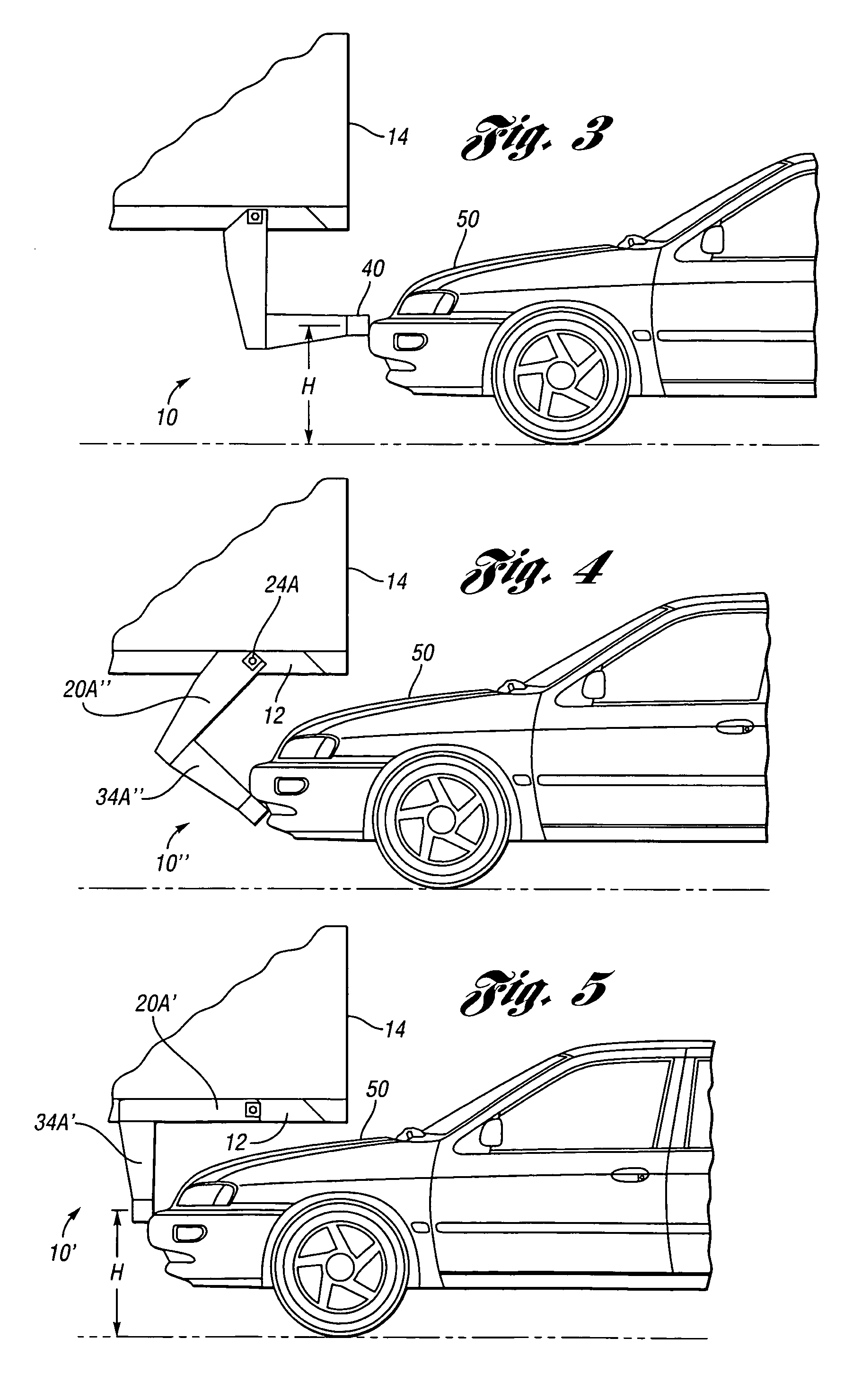
[0028]Referring to the drawings, wherein like reference numerals refer to like components, FIG. 1 shows an underride protection bumper 10 mounted to trailer structure 12A, 12B of a trailer (the trailer 14 being shown in FIG. 2). Structures 12A, 12B are preferably rails of a sliding tandem mechanism that allows a tandem axle suspension to be moved back and forth at the rear of a trailer, for the purpose of adjusting the distribution of weight between the axles, as will be understood by those skilled in the art. However, the trailer structure 12A, 12B may be any underbody or side trailer structure.

[0029]The bumper 10 includes first and second trailer attachment members 16A and 16B. The trailer attachment members 16A, 16B are also referred to herein as energy-absorbing structures. Each of the trailer attachment members 16A, 16B includes a respective proximal portion 20A, 20B which is also referred to herein as an upper or vertical portion or arm. The vertical arms 20A, 20B are preferab...


PUM


Abstract

An underride protection bumper for a trailer is provided which functions as two separate bumpers during different stages of impact to provide optimal energy absorption, impact vehicle ride-down and underride protection characteristics. Another underride protection bumper provides a support member extending diagonally inboard to counteract inboard-directed forces on trailer attachment member, thereby absorbing impact energy and minimizing underride of an impacting vehicle.

Description

CROSS-REFERENCE TO RELATED APPLICATIONS[0001]This Application claims the benefit of U.S. Provisional Application No. 60 / 634,347, filed Dec. 8, 2004, which is hereby incorporated by reference in its entirety.TECHNICAL FIELD[0002]This invention relates to an underride protection bumper for a truck or truck trailer.BACKGROUND OF THE INVENTION[0003]Truck trailers typically have a higher elevation than passenger vehicles. This presents a risk that a passenger vehicle will underride the trailer in an accident, potentially resulting in damage to the underriding vehicle and injury to occupants therein. Accordingly, Federal Motor Vehicle Safety Standards (FMVSS) require the installation of underride guards or bumpers on certain trailers. The underride guards must comply with certain deflection and energy absorption requirements. The art continues to strive for the design of an underride protection bumper that absorbs impacting energy and prevents vehicle underride in optimal fashion.SUMMARY ...

Claims


Application Information

Patent Timeline
Patent Type & Authority Patents(United States)
IPC IPC(8): B60R19/38
CPCB60R19/565B60R19/56B60R19/04B60R19/26B60R19/34B60R2021/0023B60R2021/0011
Inventor GOERTZ, ALAN R.
Owner GOERTZ ALAN R
Why Eureka
Try Eureka