Connector with improved shielding member

a shielding member and connector technology, applied in the direction of coupling device connection, coupling earth/shielding arrangement, two-part coupling device, etc., can solve the problems of easy interference of shielding parts, easy damage to shielding parts, and difficult to secure much space for mounting camera modules, etc., to achieve the effect of protecting the electrical connector from electro-magnetic interferen

Inactive Publication Date: 2006-08-08
HON HAI PRECISION IND CO LTD
View PDF5 Cites 45 Cited by
  • Summary
  • Abstract
  • Description
  • Claims
  • Application Information

AI Technical Summary

Benefits of technology

[0008]An object of the present invention is to provide an electrical connector with a shielding

Problems solved by technology

However, the solder portions of the contacts extend through the bottom shielding portion of the shielding member to expose out for being soldered on a substrate induce that the solder portions are easily affected by Electro-Magnetic waves produced by other electronic elements.
Further, with the tendency toward miniaturizi

Method used


Image

  • Connector with improved shielding member
  • Connector with improved shielding member
  • Connector with improved shielding member

Examples


Embodiment Construction

[0018]Reference will now be made to the drawing figures to describe the preferred embodiment of the present invention in detail.

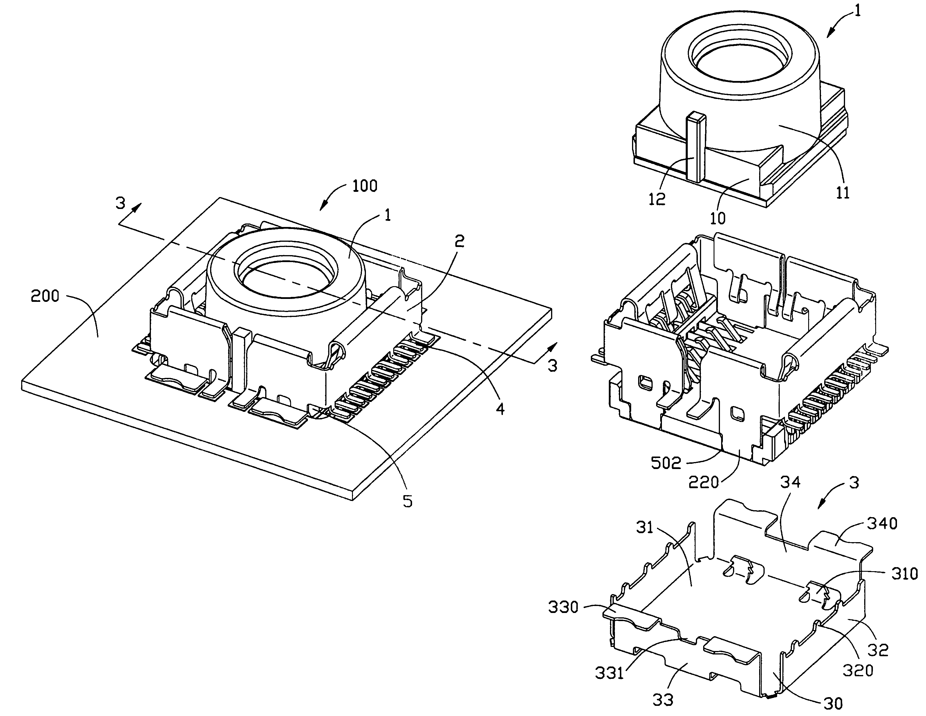
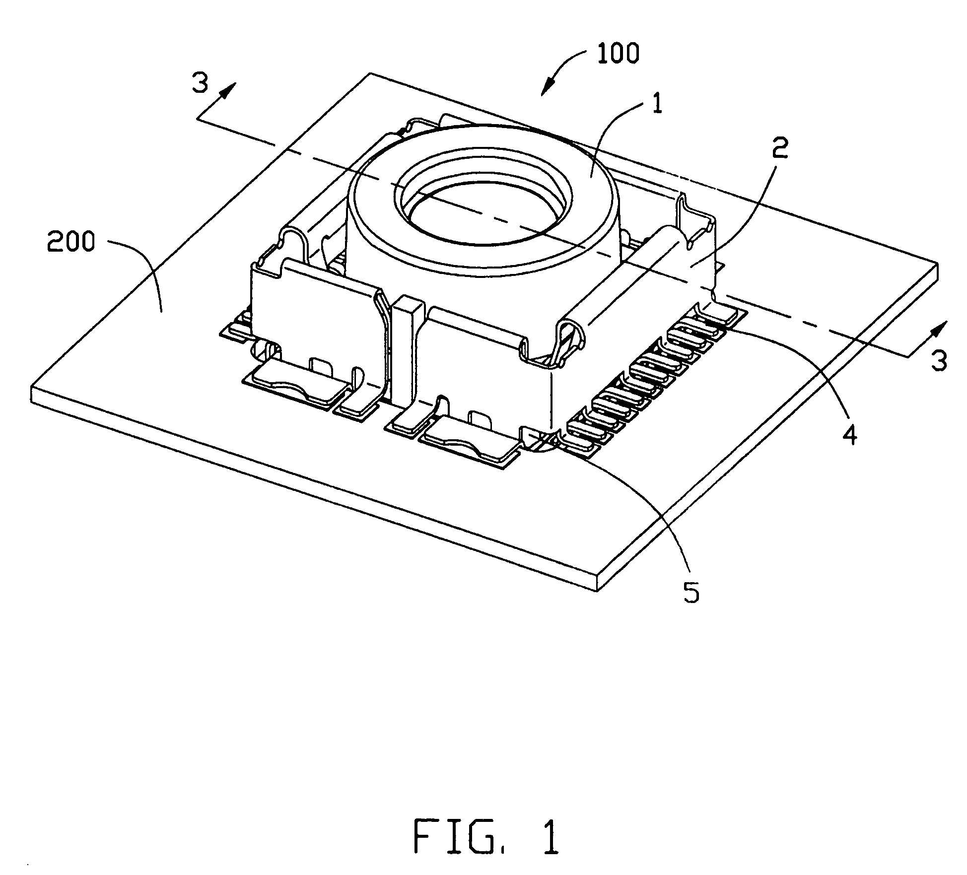
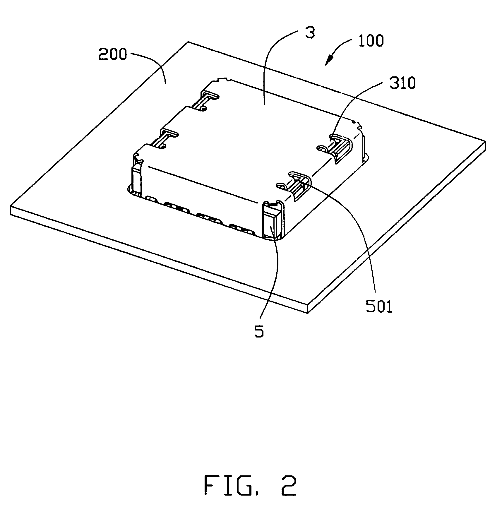
[0019]Referring to FIGS. 1, 2 and 3, an electrical connector 100 for connecting an electronic element with a printed circuit board (PCB) 200. In this embodiment, the electronic element is a camera module 1. The electrical connector 100 comprises a shielding member, an insulated housing 5 and a plurality of electrical contacts 5 retained in the housing 5.

[0020]Referring to FIGS. 4 and 6, the shielding member consists of an upper shell 2 and a lower shell 3. The upper shell 2 consists of a pair of metal frame 20 which are symmetrically and separately arranged to surround a receiving cavity 21. The two metal frame 20 have same configuration ad each has three vertical walls that are a front wall 22, a rear wall 23 opposite and parallel to the front wall 22 and a side wall 24 jointing the front wall 22 with the rear wall 23. Each vertical wall comprises a fold p...


PUM


Abstract

An electrical connector (100) adapted for electrically connecting an electronic element (1) such as a camera module with a substrate (200) comprises a shielding member (2, 3), an insulated housing (5) and a number of contacts (4) retained in the housing. Each contact comprises a contact portion (41) for electrically contacting with the camera module and a solder portion (44) extending out the housing for being soldered on the substrate. The shielding member surrounds the housing to prevent the contact from unexpected Electro Magnetic Interference and comprises a plurality solder legs soldered on the substrate. The solder legs are arranged among the solder portions of the contacts. Typically, the distance between every two adjacent solder legs is not greater than 2.5 millimeters. Therefore, the shielding member can effectively prevents various unexpected interference affecting signal transmission of the camera module.

Description

BACKGROUND OF THE INVENTION[0001]1. Field of the Invention[0002]The present invention relates to an electrical connector, and more particularly to an electrical connector for mounting a camera module on a substrate such as a printed circuit board, a printed wiring board and the like.[0003]2. Description of Related Art[0004]Due to the development of the information and communication technology industry, various types of portable wireless terminals such as mobile phones, Personal Digital Assistant always simply called as PDA and so forth. Said terminals are provided with various functions, for example, e-mail reception and transmission, Internet games and text transmission. Beyond the above basic functions, recently, image communication as a new function is introduced. As a result, said various portable wireless terminals are additionally provided with camera modules, correspondingly, electrical connectors are used for connecting with the camera modules are also provided.[0005]U.S. Pa...

Claims


Application Information

Patent Timeline
IPC IPC(8): H01R13/648
CPCH01R13/65802H01R12/716H01R23/6873H01R13/6582H01R13/6594
Inventor YANG, MENG-HUAN
Owner HON HAI PRECISION IND CO LTD
Why Eureka
Try Eureka