Differentiated rigidity swimming fin with hydrodynamically designed rearward shoe strap connection

a technology of hydrodynamic design and swimming fins, applied in swimming, swimming fins, sport apparatus, etc., can solve the problems of affecting the efficiency of conventional swimming fins, etc., and achieve the effects of improving propulsion efficiency, improving the structure of swimming fins, and limiting any encroachmen

Inactive Publication Date: 2006-08-08
CRESSI SUB
View PDF22 Cites 16 Cited by
  • Summary
  • Abstract
  • Description
  • Claims
  • Application Information

AI Technical Summary

Benefits of technology

[0008]An object of the present invention is to provide a fin for swimmers having improved propulsion efficiency as compared to conventional fins.
[0009]These objects and advantages are attained by improving the structure of the fin from both mechanical and hydrodynamic points of view. In particular, elastic hinges extending in both the longitudinal and diagonal direction are also provided on the blade of the fin to enable deformation of transverse sections of the fin. Moreover, along side portions of the shoe, sideways

Problems solved by technology

More particularly, it has been found that the efficiency of a conventional swimming fin has a first limitation in that the rigid blade generally bends only in a plane substantially at right angles to the plane of the undeformed blade, its transverse sections being maintained substantially constant.
Sec

Method used


Image

  • Differentiated rigidity swimming fin with hydrodynamically designed rearward shoe strap connection
  • Differentiated rigidity swimming fin with hydrodynamically designed rearward shoe strap connection
  • Differentiated rigidity swimming fin with hydrodynamically designed rearward shoe strap connection

Examples


Embodiment Construction

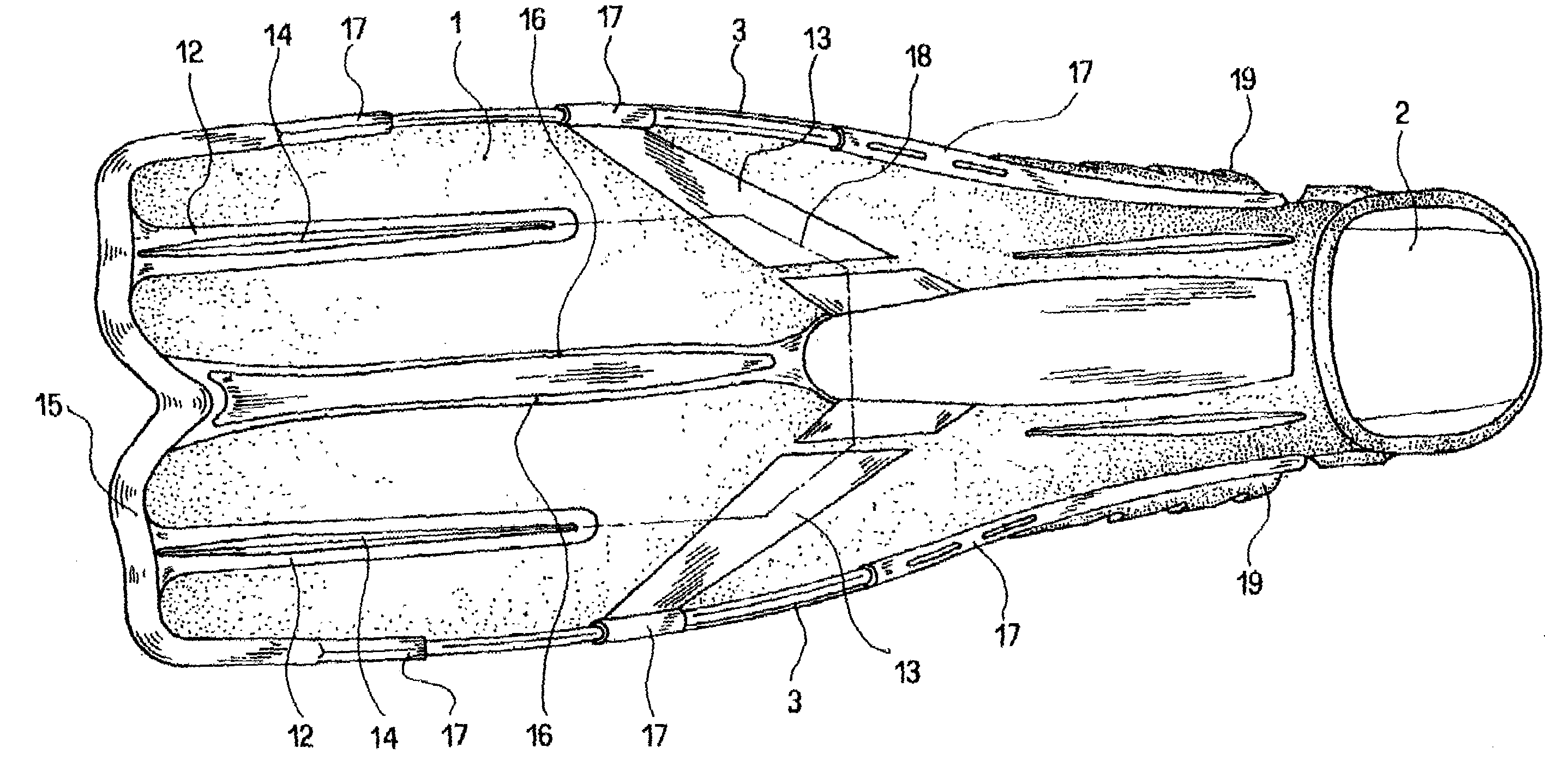
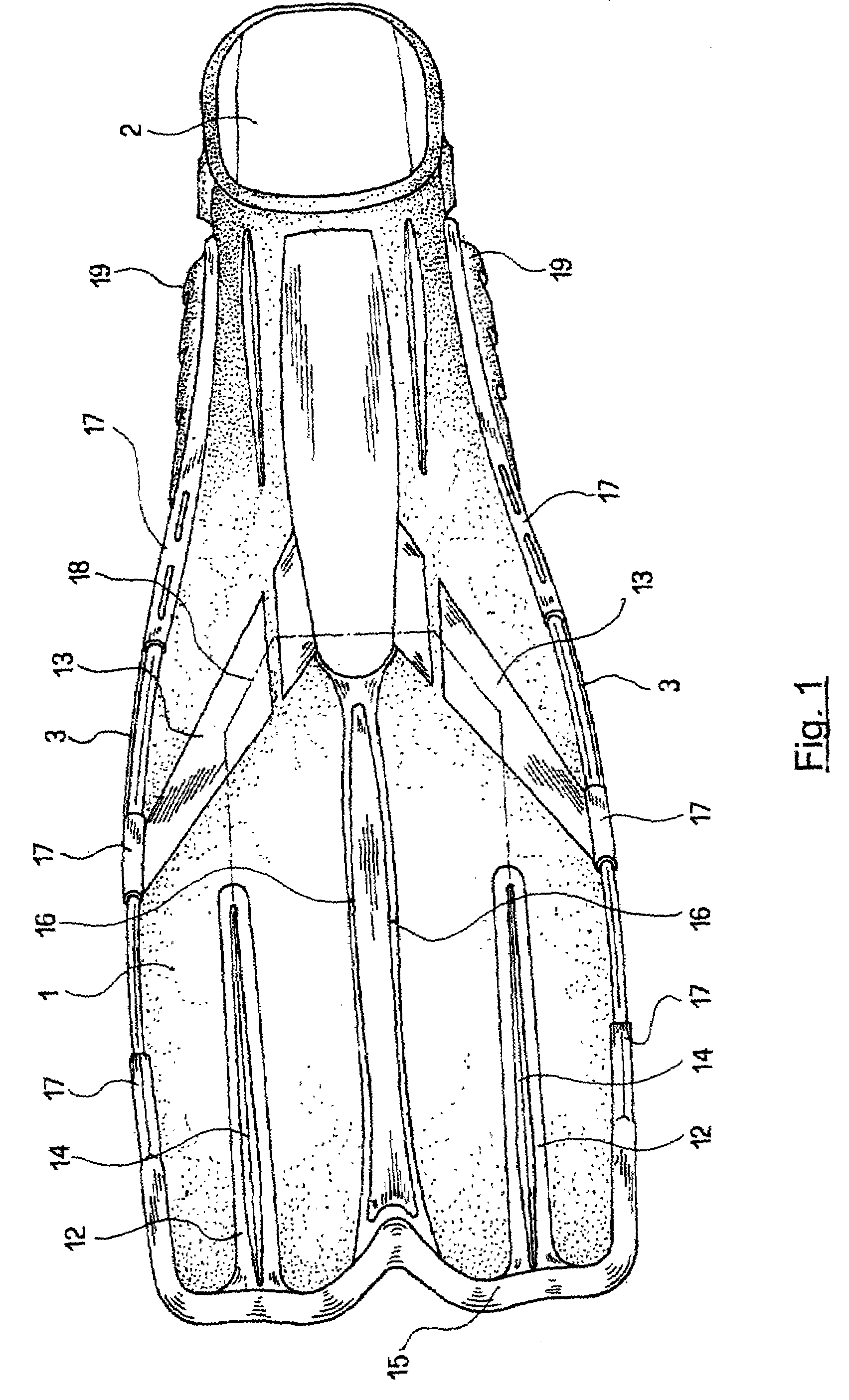
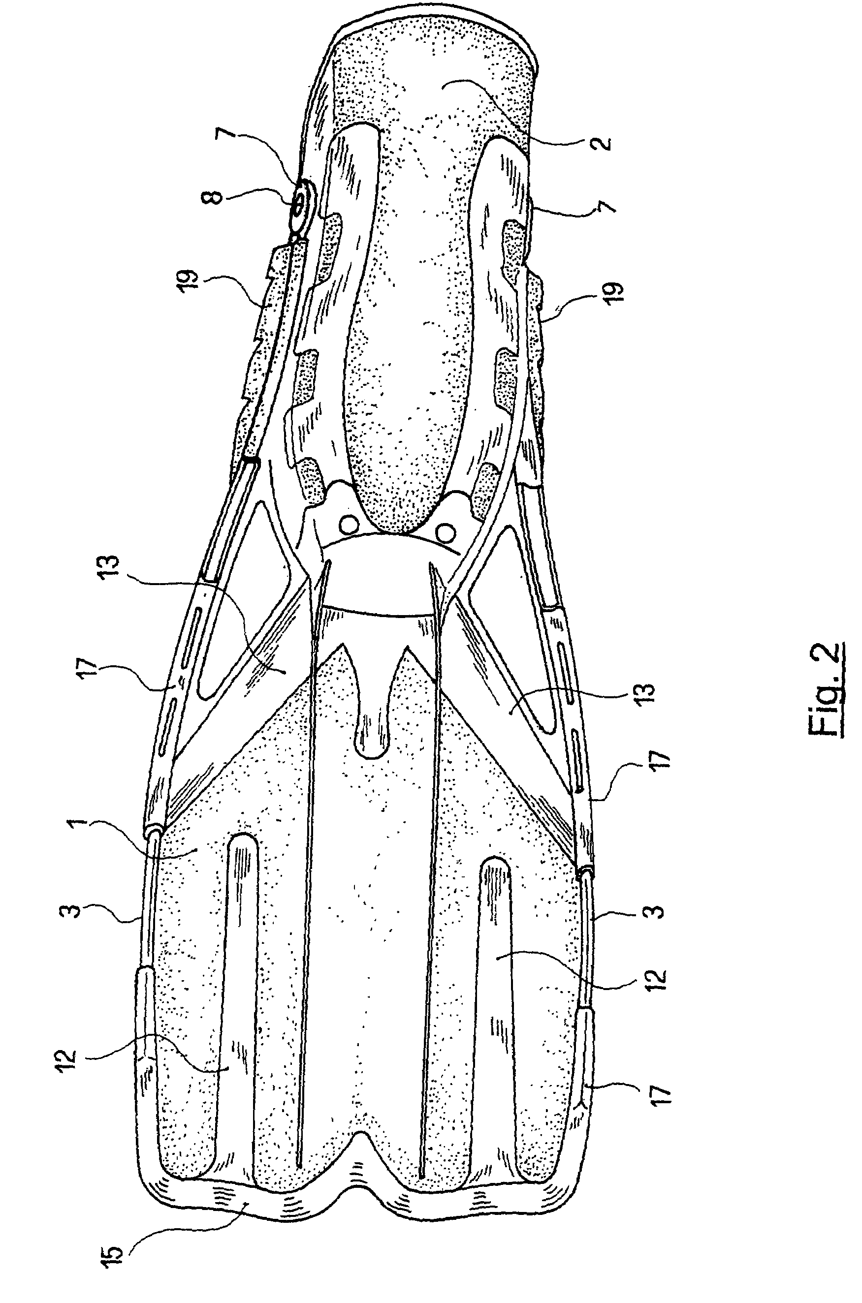
[0019]Referring now to the drawings and, more particularly, to FIGS. 1–4, there is shown generally a specific, illustrative differentiated rigidity swimming fin with hydronamically designed rearward shoe strap connection. According to one aspect of the present invention, the fin comprises a paddle or blade 1 constructed of a relatively rigid material, a shoe 2 made of a relatively yielding material, and a plurality of generally lateral ribs 3, preferably two, extending along the edges of blade 1, both above and below the plane of the blade, and constructed of a material having rigidity characteristics intermediate between those of the blade and the shoe. Preferably, the fin is produced in three successive molding stages: First, the blade is molded, the resulting product being shown in FIG. 5; second, the lateral ribs are molded, so as to obtain the product shown in FIG. 6; and three, the shoe and the remaining parts of the flipper, made of a relatively yielding material, are molded ...


PUM


Abstract

A swimming flipper comprising a blade (1) made of relatively rigid material, a shoe (2) made of relatively yielding material and at least a pair of lateral ribs (3) extending along the edges of the blade. On the blade there are provided at least two longitudinal slots (9) arranged symmetrically with respect to the longitudinal axis of the flipper and two openings (11) extending diagonally from the shoe towards the lateral edges of the blade. The slots and the openings are filled with a relatively yielding material in the form of flattened ribs (12, 13).

Description

FIELD OF THE INVENTION[0001]The present invention relates generally to articles for self-propulsion and, more particularly, to foot mounted articles for effecting movement through fluid media or the like.BACKGROUND OF THE INVENTION[0002]Conventional foot mounted articles for effecting movement through fluid media. e.g., fins for swimming through water, generally take the form of fins which comprise a blade constructed of a relatively rigid material connected at the rear to a shoe made of a relatively yielding material. As set forth in the present description, the term “relatively rigid material” refers to a material such as, for example, polypropylene or the equivalent, while the term “relatively yielding material” in the present description refers to a material such as a thermoplastic polymer based essentially on SEBS elastomers or the equivalent.[0003]Such materials are commonly used in the production of fins for swimmers.[0004]In order to protect against scratches and cuts that m...

Claims


Application Information

Patent Timeline
IPC IPC(8): A63B31/08A63B31/11
CPCA63B31/11
Inventor GODOY, CARLOS ALBERTO
Owner CRESSI SUB
Why Eureka
Try Eureka