Particle formation

a particle and particle technology, applied in the field of particle formation, can solve the problems that authors have not appeared to have achieved such high velocities, and achieve the effect of reducing the risk of apparatus blockage, or substantially eliminating or at least reducing the risk of blockag

Inactive Publication Date: 2006-08-08
NEKTAR THERAPEUTICS INC
View PDF37 Cites 17 Cited by
  • Summary
  • Abstract
  • Description
  • Claims
  • Application Information

AI Technical Summary

Benefits of technology

[0034]The near-sonic, sonic or supersonic anti-solvent velocity is ideally achieved, in the method of the present invention, simply by the use of appropriate anti-solvent flow rates, back pressures and / or operating temperatures, and without the aid of mechanical, electrical and / or magnetic input such as for example from impellers, impinging surfaces especially within the anti-solvent introducing means, electrical transducers and the like. Introducing the anti-solvent via a convergent nozzle, ideally as a single fluid stream, may also help in the achievement of appropriate fluid velocities. Further “energising” fluid streams, such as those required in the method of WO-97 / 31691, are not then needed in order to achieve the desired level of control over the contact between the target solution / suspension and the anti-solvent fluid.
[0068]The anti-solvent flow rate will also generally be chosen to ensure an excess of the anti-solvent over the vehicle when the fluids come into contact, to minimise the risk of the vehicle re-dissolving and / or agglomerating the particles formed. At the point of extraction of the vehicle it may constitute from 1 to 80 mole %, preferably 50 mole % or less or 30 mole % or less, more preferably from 1 to 20 mole % and most preferably from 1 to 5 mole %, of the compressed fluid mixture formed.

Problems solved by technology

However, the authors do not appear ever to have achieved such high velocities in their experimental examples.

Method used


Image

  • Particle formation
  • Particle formation
  • Particle formation

Examples


examples

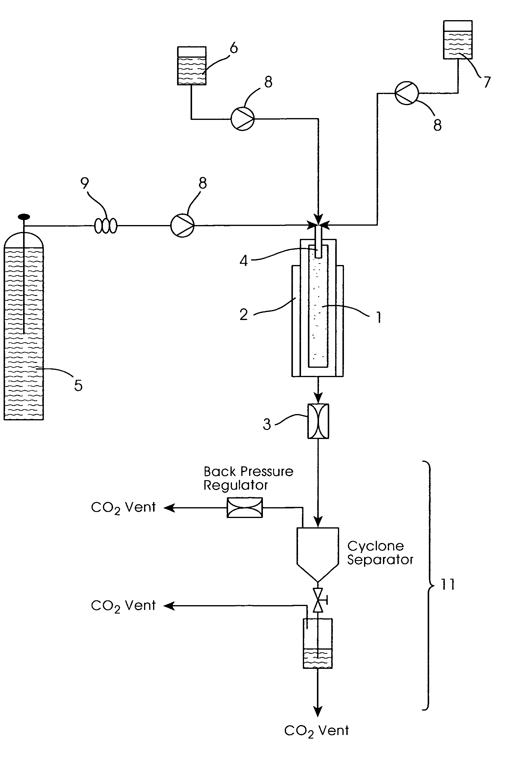
[0108]Apparatus as shown in FIG. 2, incorporating a fluid inlet assembly as shown in FIGS. 3 to 5, was used to carry out particle formation methods in accordance with the invention. The nozzle 21 comprised a fluid inlet tube of internal diameter 1.6 mm and an outlet of diameter 0.2 mm. The internal bore at the end of the inlet tube 23 was 0.125 mm. The vertical separation “d” between the nozzle and tube outlets was varied between 0 and 8 mm, “0” representing the situation where the solution tube 23 contacted the lower end of the nozzle 21.

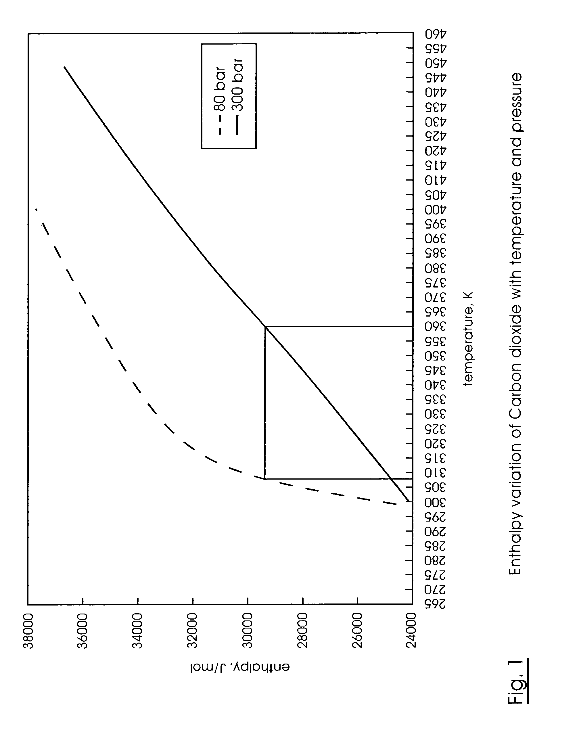
[0109]Supercritical carbon dioxide was used as the anti-solvent. It was pumped at a flow rate (of liquid CO2, prior to passing through a heater) of 200 g / min. Its temperature on entry into the nozzle 21 was 356 K (83° C.).

[0110]The pressure in the particle formation vessel 1 (capacity 2 liters) was maintained at 80 bar and 309–313 K (36–40° C.). The CO2 back pressure was between 250 and 300 bar. These conditions created a sonic or supersonic CO2 ve...

examples a

[0111]Various target compounds were dissolved in appropriate solvents and introduced into the apparatus via tube 23. The distance “d” between the outlets of the anti-solvent nozzle and the solution inlet tube was kept constant at 4 mm. Particle formation was allowed to occur by the action of the CO2 anti-solvent, and the products collected in the vessel 1. The products were assessed by scanning electron microscopy (SEM) and in most cases their particle sizes analysed using an Aerosizer™ and / or Sympatec™ system.

[0112]The results of these experiments are shown in Table 1 below.

[0113]

TABLE 1TargetTargetsolutionsolutionProduct sizeProduct sizeExptconcentrationflow rate(Aerosizer ™)(Sympatec ™)no.Target solution(% w / v)(ml / min)(μm)(μm)A1Compound I in342.84—methanolA2Compound II in1.754—5.75methanolA3Compound III in30.51.397.99DMFA4Compound IV in0.854——DMFA5Compound V in31—4.6 DMSOA6Compound VI in510.972.5 THF

[0114]SEM photographs of the products of Experiments A1, A2, A5 and A6 are shown ...

examples b

[0115]In these experiments, the distance “d” between the outlets of the anti-solvent nozzle 21 and the solution inlet tube 23 was varied between 0 and 8 mm. In practice, the “0” separation represented the thickness of the inlet tube wall—in other words, as close to zero as was possible without cutting into the nozzle wall. The target solution was 3% w / v compound I in methanol; its flow rate into the particle formation vessel 1 was 4 ml / min.

[0116]The results are shown in Table 2 below.

[0117]

TABLE 2DistanceProduct sizeExpt“d”(Aerosizer ™)no.(mm)(μm)B103.21B242.84B383.63

[0118]The particle size distributions (by Aerosizer™) for the products of Examples B1, B2 and B3 are shown in FIGS. 10A and 10B, 11A and 11B, and 12A and 12B respectively.


PUM

PropertyMeasurementUnit
pressureaaaaaaaaaa
temperatureaaaaaaaaaa
critical temperature Tcaaaaaaaaaa

Abstract

Method for preparing a target substance in particulate form, comprising introducing into a particle formation vessel, through separate first and second fluid inlets respectively, (a) a “target solution / suspension” of the substance in a fluid vehicle and (b) a compressed fluid anti-solvent, and allowing the anti-solvent to extract the vehicle so as to form particles of the substance, wherein the anti-solvent fluid has a sonic, near-sonic or supersonic velocity as it enters the vessel, and wherein the anti-solvent and the target solution / suspension enter the vessel at different locations and meet downstream (in the direction of anti-solvent flow) of the second fluid inlet. Also provided is apparatus for use in such a method.

Description

FIELD OF THE INVENTION[0001]This invention relates to methods and apparatus for forming particles of a target substance.BACKGROUND TO THE INVENTION[0002]It is known to use a compressed fluid, typically a supercritical or near-critical fluid, as an anti-solvent to precipitate particles of a substance of interest (a “target substance”) from solution or suspension. The basic technique is known as “GAS” (Gas Anti-Solvent) precipitation [Gallagher et al, “Supercritical Fluid Science and Technology”, ACS Symp. Ser., 406, p334 (1989)]. Versions of it have been disclosed for instance in EP-0 322 687 and WO-90 / 03782, which are hereby incorporated in their entirety by reference.[0003]In one particular version known as SEDS™ (Solution Enhanced Dispersion by Supercritical fluids), a target substance is dissolved or suspended in an appropriate fluid vehicle, and the resulting “target solution / suspension” then co-introduced into a particle formation vessel with an anti-solvent fluid (usually supe...

Claims


Application Information

Patent Timeline
Patent Type & Authority Patents(United States)
IPC IPC(8): B29B9/00B01J2/04
CPCB01J2/04
Inventor PALAKODATY, SRINIVASKORDIKOWSKI, ANDREASGILBERT, DARREN
Owner NEKTAR THERAPEUTICS INC
Why Eureka
Try Eureka