Cable management system with patch panel

a management system and patch panel technology, applied in electrical equipment, bus-bar/wiring layouts, substation/switching arrangement details, etc., can solve the problems of limited patch panel access, difficult maintenance, and inability to densely stack conventional bracket mounted patch panels, etc., to achieve simple and inexpensive manufacturing

Active Publication Date: 2006-08-08
HUBBELL INC
View PDF32 Cites 84 Cited by
  • Summary
  • Abstract
  • Description
  • Claims
  • Application Information

AI Technical Summary

Benefits of technology

[0006]Accordingly, an object of this invention is to provide a cable management system having easy access which is simple and inexpensive to manufacture.
[0007]Another object of this invention is to provide a cable management system that reduces cable congestion and increases airflow to the space.

Problems solved by technology

When individual conductors are to be coupled to the insulation displacement contacts on the jacks or connectors, the limited space available when the patch panels are mounted in a rack makes maintenance difficult.
Also, conventional bracket mounted patch panels cannot be densely stacked and provide limited patch panel access.

Method used


Image

  • Cable management system with patch panel
  • Cable management system with patch panel
  • Cable management system with patch panel

Examples


first embodiment

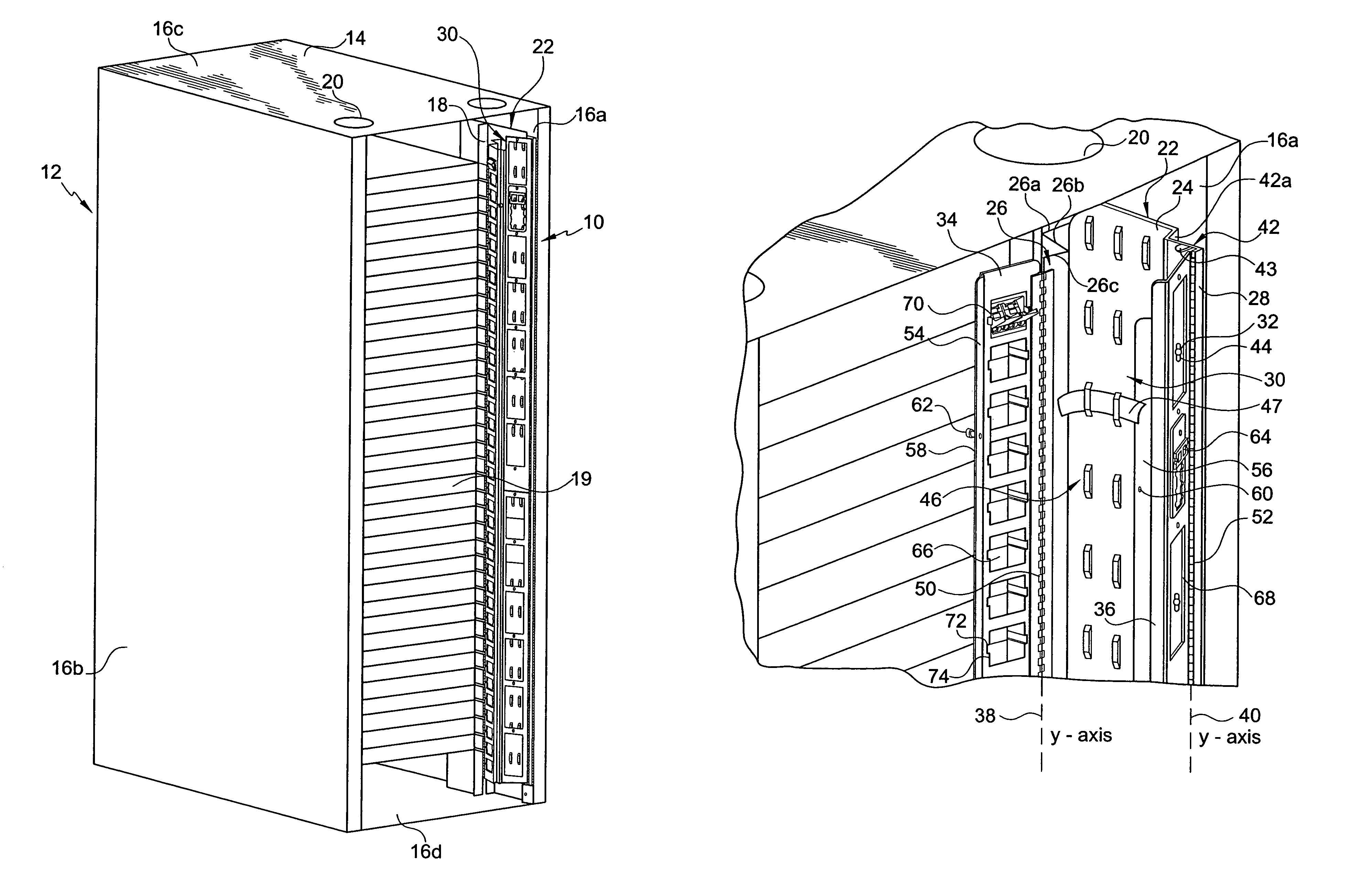
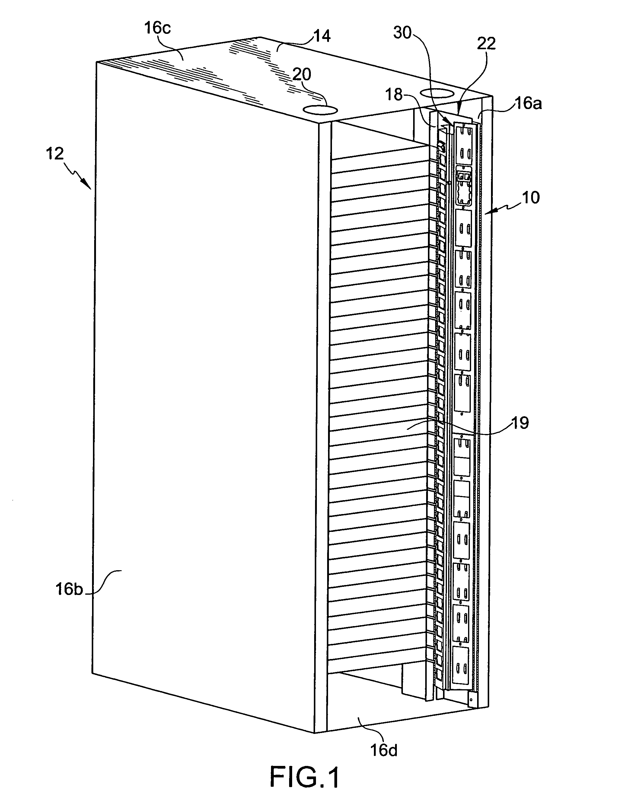
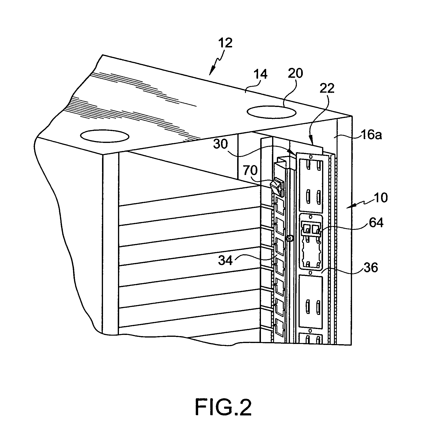
[0021]Referring initially to the invention illustrated in FIGS. 1–5, a patch panel assembly 10 is in a cable management system 12 in the form of a server cabinet or rack 14. The rack 14 includes walls 16a–d and an electronic device support 18 for electronic devices 19, such as servers. Cable management system 12 includes a bracket 22 having a base 24 extending between first and second side walls 26, 28 (FIG. 3). Bracket 22 defines a cable receiving passageway 30. First and second patch panels 34, 36 are coupled to the first and second side walls 26, 28, respectively, for pivotal movement about first and second vertical pivot axes 38, 40 between an open position (FIG. 3) and a closed position (FIG. 4).

[0022]Rack 14 can be constructed of any suitable material for forming a support frame, preferably having a top wall 16c, a bottom wall 16d, side walls 16a–b, and an electronic device support 18. Each wall 16a–d may include a knockout 20 for use as a cable receiving aperture or for facil...

third embodiment

[0038]A patch panel assembly 310 according to the present invention is disclosed in FIGS. 7 and 8. In this embodiment, patch panel assembly 310 includes a bracket 322 having a base 324 with integrated first and second side walls 342, 343. Side walls 342, 343 form a continuous or unitary member therewith. First side wall 342 extends perpendicularly from a top surface 324a of base 324. A patch panel stop member 344 extends from the first side wall 342 in a direction parallel to the top edge of base 324 for limiting rotation of patch panel 336. An edge of first side wall 342 is connected to a piano-type hinge 352 for connecting patch panel 336 to the base 324. Second side wall 343 is substantially C-shaped. Second side wall 343 has a first section 343a which extends perpendicularly from top surface 324a and a second section 343b which extends substantially parallel with top surface 324a. Patch panel 334 is connected to one side of the second section 343b by a piano-type hinge 350.

[0039...


PUM


Abstract

A patch panel assembly having a bracket with a base extending between first and second side walls. The bracket defines a cable receiving passageway. First and second patch panels are coupled to the first and second side walls for pivotal movement about first and second vertical pivot axes between open and closed positions. The patch panels are selectively engageable with one another in their closed positions for limiting access across the cable receiving passageway.

Description

FIELD OF THE INVENTION[0001]The present invention relates to a cable management system with a patch panel assembly for organizing and simplifying wiring and connections in an electronic device, such as a typical server cabinet. More specifically, first and second patch panels are mounted to a support frame for pivoting about two laterally spaced, substantially parallel vertical axes.BACKGROUND OF THE INVENTION[0002]Patch panels or cross-connect products provide a centralized point for connecting voice and / or data lines. Patch panels include a plurality of energy transmission connectors, e.g., electrical connectors and / or fiber optic cable connectors. Patch panels are commonly located in confined, relatively remote areas, such as termination closets. Installers generally perform wire terminations with little room to maneuver patch panels or themselves. Therefore, patch panel assemblies must be compact to save space, and to facilitate installer access to each patch panel.[0003]Each co...

Claims


Application Information

Patent Timeline
Patent Type & Authority Patents(United States)
IPC IPC(8): H02G3/04
CPCH02G3/0431
Inventor HERRING, NATHANIEL L.BAXTER, ROBERT C.KIERSTEAD, GLENN T.
Owner HUBBELL INC
Why Eureka
Try Eureka