
Oven

a technology of oven and oven body, which is applied in the field of oven, can solve the problems of unsafe user touching the door after cooking, increased energy consumption, and increased heat loss, and achieve the effect of preventing heat transfer

Inactive Publication Date: 2006-08-08
SAMSUNG ELECTRONICS CO LTD
View PDF8 Cites 12 Cited by
  • Summary
  • Abstract
  • Description
  • Claims
  • Application Information

AI Technical Summary

Benefits of technology

[0010]Accordingly, it is an aspect of the invention to provide an oven including a cooking chamber having a plurality of vertically partitioned cooking spaces, that is capable of preventing heat transfer from one cooking space having relatively high temperature to another cooking space having relatively low temperature along opposite side plates of the cooking chamber.
[0012]The foregoing and / or other aspects of the present invention are achieved by providing an oven including a cooking chamber, a partition horizontally disposed in the cooking chamber to partition the cooking chamber into first and second cooking spaces; and an insulating unit mounted at each side plate of the cooking chamber to prevent heat transfer between the first and second cooking spaces along each side plate of the cooking chamber.
[0022]It is another aspect of the present invention to provide an oven including a cooking chamber, a partition horizontally disposed in the cooking chamber to partition the cooking chamber into first and second cooking spaces, and a cooling unit mounted at each side plate of the cooking chamber to minimize heat transfer between the first and second cooking spaces along each side plate of the cooking chamber.

Problems solved by technology

As the heat transfer is carried out between the cooking spaces along the opposite side plates of the cooking chamber as described above, heat loss is generated, and therefore, energy consumption is increased.
Further, the door of the oven is maintained at high temperature thereby making it unsafe for a user to touch the door after cooking is completed.

Method used


Image

  • Oven
  • Oven
  • Oven

Examples


Embodiment Construction

[0033]Reference will now be made in detail to the embodiment of the present invention, examples of which are illustrated in the accompanying drawings, wherein like reference numerals refer to like elements throughout. The embodiment is described below to explain the present invention by referring to the figures.

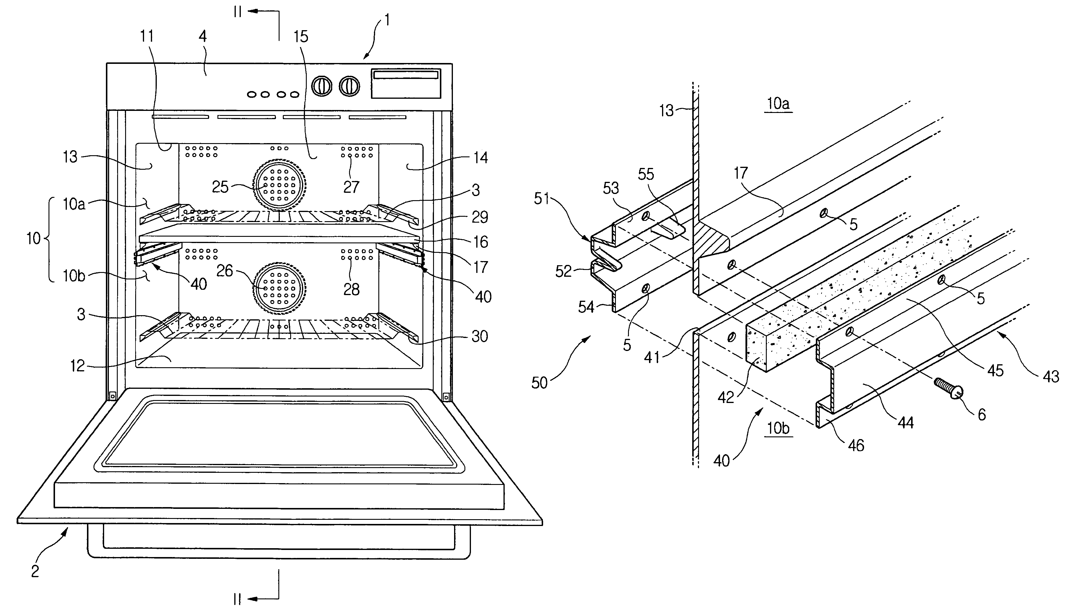
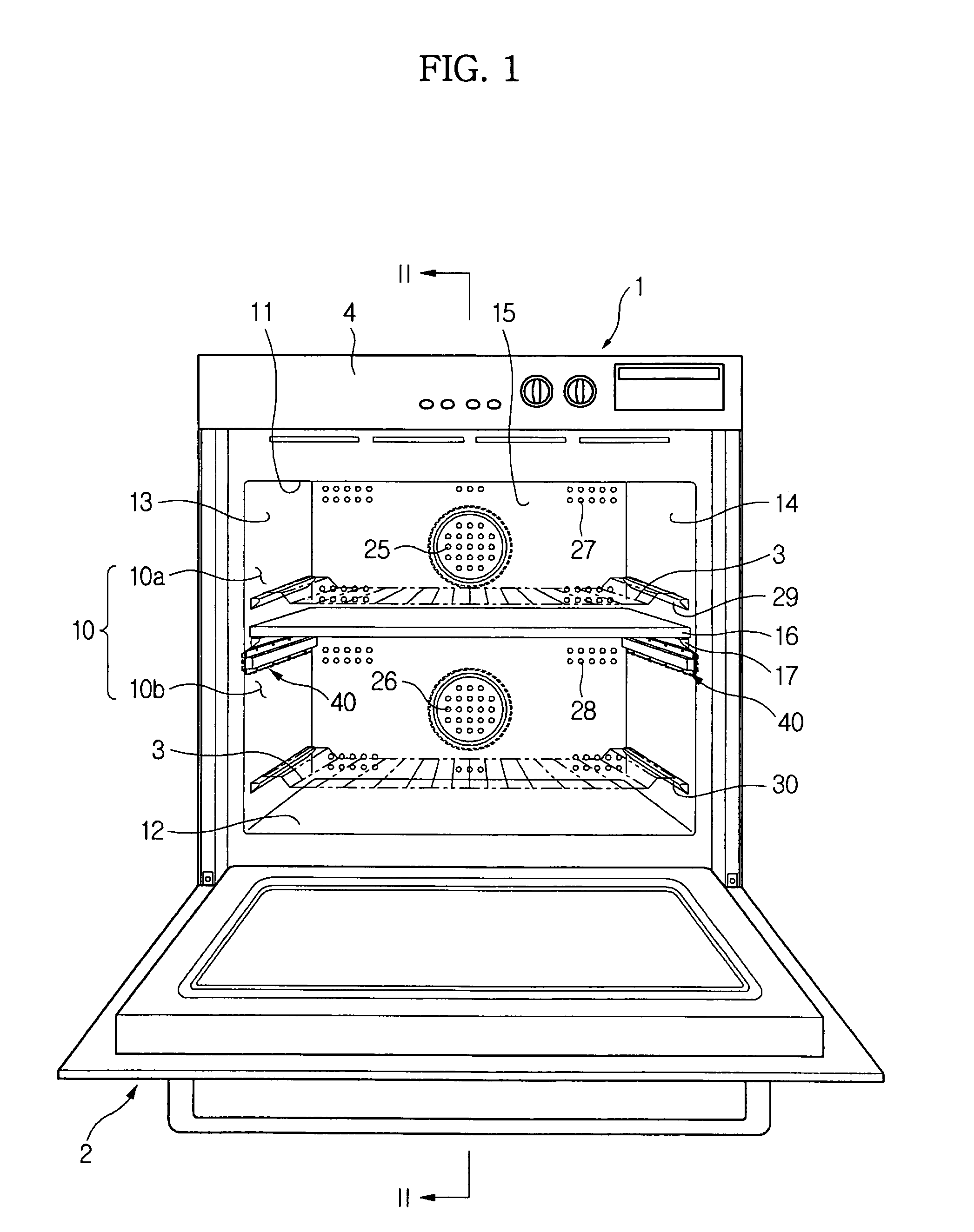
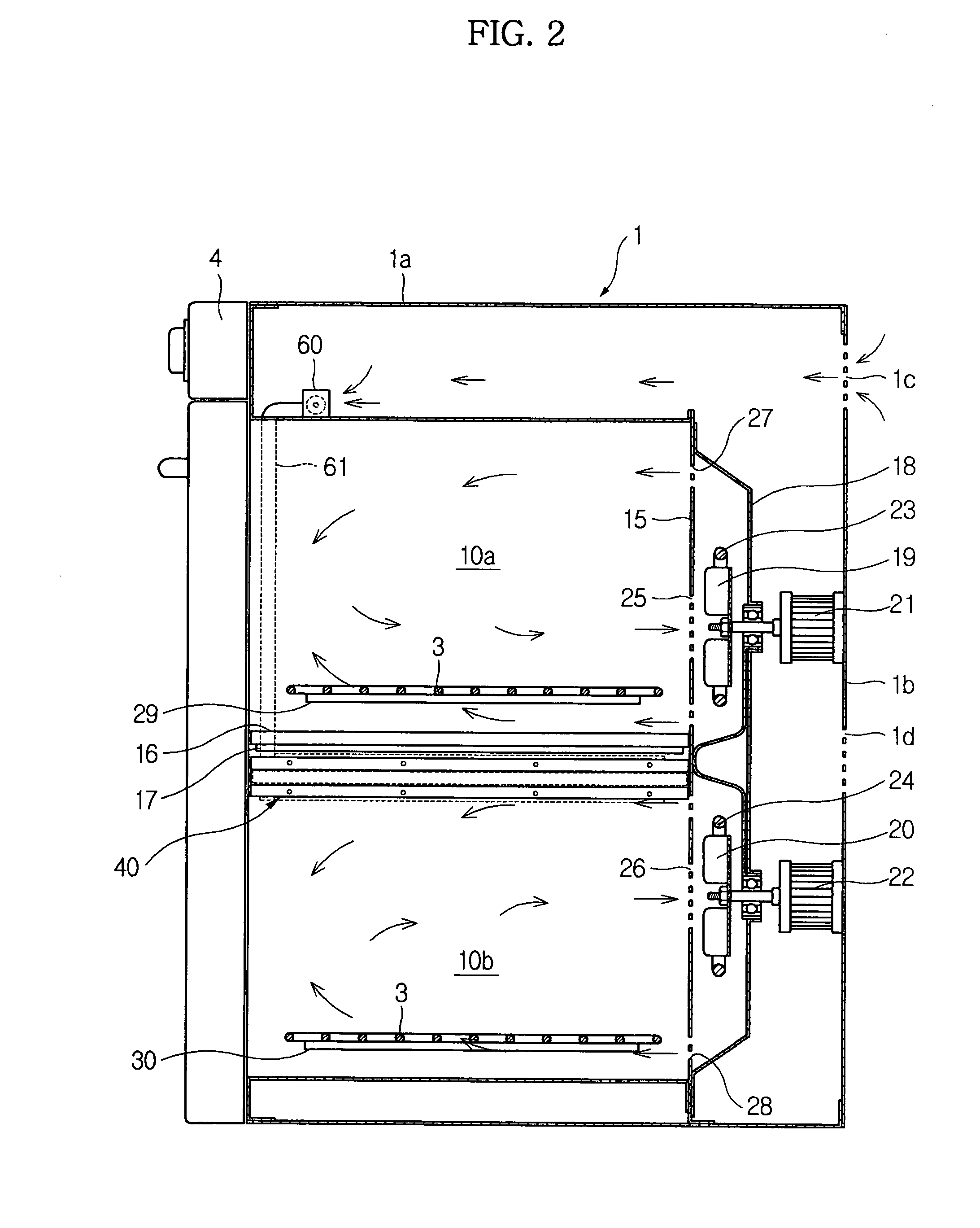
[0034]FIG. 1 is a front view schematically illustrating the structure of an oven according to the present invention, and FIG. 2 is a sectional view taken along line II—II of FIG. 1.

[0035]As shown in FIGS. 1 and 2, the oven comprises a cabinet 1, formed of a box-shape having an opened front surface, including a cooking chamber 10 defined therein, and a door 2 hingedly connected with a lower end of the cabinet 1, to open and close the opened front surface of the cabinet 1. The cabinet 1 and the door 2 together form an outer appearance of the oven.

[0036]The cooking chamber 10 comprises a top plate 11, a bottom plate 12, a left side plate 13, a right side plate 14, and a rear pla...


PUM


Abstract

An oven capable of preventing heat transfer from one cooking space having relatively high temperature to another cooking space having relatively low temperature along each side plate of a cooking chamber having a plurality of partitioned cooking spaces. The oven includes an insulating unit and a cooling unit mounted at each side plate to prevent heat transfer between first and second cooking spaces along each side plate. The insulating unit includes a slit formed right under the partition, an insulating member fitted in the slit, and a supporting member attached to the inside of each side plate. The cooling unit includes an air guide member attached to the outside of each side plate to cover the insulating member, and a blowing fan connected to the air guide member to forcibly blow outside air to the air guide member.

Description

CROSS-REFERENCE TO RELATED APPLICATIONS[0001]This application claims the benefit of Korean Patent Application No. 2005-48925, filed on Jun. 8, 2005 in the Korean Intellectual Property Office, the disclosure of which is incorporated herein by reference.BACKGROUND OF THE INVENTION[0002]1. Field of the Invention[0003]The present invention relates to an oven, and, more particularly, to an oven that is capable of preventing heat transfer from one cooking space having relatively high temperature to another cooking space having relatively low temperature along opposite side plates of a cooking chamber. The cooking chamber includes a plurality of vertically partitioned cooking spaces by the provision of insulating units and cooling units, which are mounted at the opposite side plates of the cooking chamber.[0004]2. Description of the Related Art[0005]Conventional ovens are classified into different types, such as a microwave oven to cook food using microwaves, an electric oven to cook food ...

Claims


Application Information

Patent Timeline
Patent Type & Authority Patents(United States)
IPC IPC(8): F24C15/16A21B3/00
CPCF24C15/006F24C15/34F24C15/325F24C15/16F24C15/18F24C15/08
Inventor KIM, CHEOL JINHWANG, YUN ICHONG, SEOK WEONCHO, PUNG YEUNHA, YU JEUBKIM, KYOUNG HOKIM, SUNG KWANGLEE, KIL YOUNGPARK, SUNG SOOKIM, TAE HOKANG, SANG HYUN
Owner SAMSUNG ELECTRONICS CO LTD
Learn More