
Method and apparatus for calibrating a sensor for highlights and for processing highlights

a technology of highlights and calibration methods, applied in the field of methods and equipment, can solve the problem that the full dynamic range cannot be communicated to the viewer through conventional optical and digital techniques, and achieve the effect of improving the dynamic range of captured images

Inactive Publication Date: 2006-08-08
MONUMENT PEAK VENTURES LLC
View PDF24 Cites 110 Cited by
  • Summary
  • Abstract
  • Description
  • Claims
  • Application Information

AI Technical Summary

Benefits of technology

[0009]It is an aspect of the invention to improve the dynamic range of a captured image using calibration techniques on the image capture system.
[0010]It is another aspect to improve the dynamic range of a captured image using signal processing operations on the captured image.
[0011]It is another aspect to electronically capture a picture that has areas that are more than ten times brighter than the whitest reflective area in the picture using a highlight sensitive sensor, and to accurately reproduce those areas electronically.

Problems solved by technology

However, this full dynamic range may not be communicated to the viewer through conventional optical and digital techniques.

Method used


Image

  • Method and apparatus for calibrating a sensor for highlights and for processing highlights
  • Method and apparatus for calibrating a sensor for highlights and for processing highlights
  • Method and apparatus for calibrating a sensor for highlights and for processing highlights

Examples


Embodiment Construction

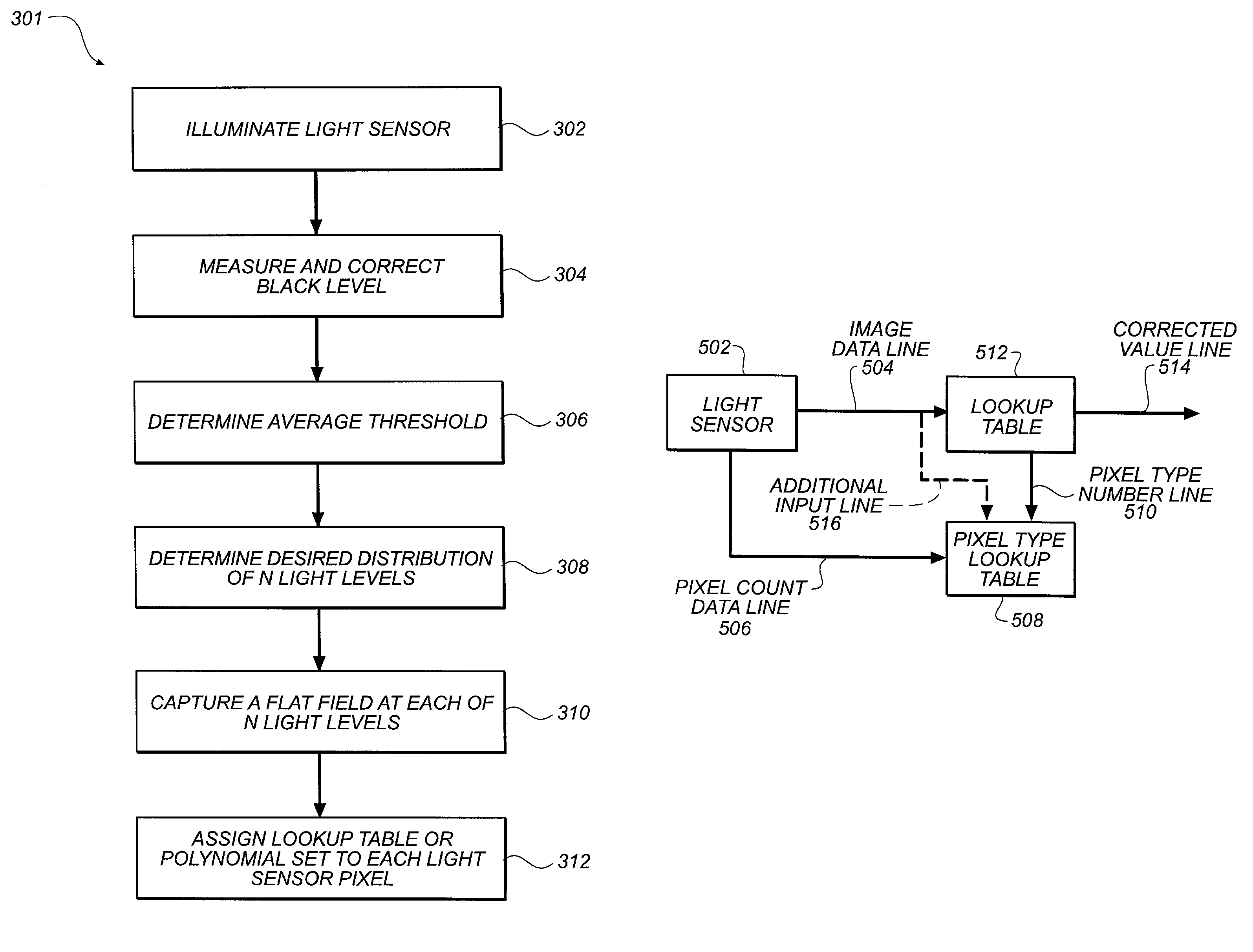
[0050]A system for increasing the dynamic range of an electronic image is disclosed. A number of different techniques can be used to impose the dynamic range of an electronic image. It is an aspect of the present invention to electronically capture a picture that has areas that are at least ten times brighter than the whitest diffuse reflective area in the picture using a highlight sensitive sensor, and to accurately reproduce those areas electronically. It is another aspect of the present invention to improve the accuracy of the dynamic range of the captured image for both electronic cameras and film based cameras using calibration operations on the image capture system. It is a further aspect of the present invention to improve the dynamic range of the captured image using signal processing operations on the captured image. Another aspect of this invention is to ensure that in highlight areas sensors and their associated systems can provide stable, reproducible and accurate data s...


PUM


Abstract

A method and apparatus for calibrating a sensor for highlights and for processing highlights is described. In an embodiment, a method includes identifying highlight regions in an image of a scene. The method further includes calculating flare intensity values for the image using the locations of the highlight regions. The method also includes subtracting the flare intensity values from the image.

Description

CROSS-REFERENCE TO RELATED APPLICATION(S)[0001]This application is related to and claims priority from a U.S. application entitled “Accurately Reproducing Image Highlights Using Electronic Sensors—Signal Processing” having Ser. No. 60 / 267,348 by MacLean et al., filed on Feb. 8, 2001, and incorporated by reference herein.BACKGROUND OF THE INVENTION[0002]1. Field of the Invention[0003]The present invention is directed to the field of processing data from electronic light sensors that are directly exposed to a scene or that are exposed to film that has captured the scene.[0004]2. Description of the Related Art[0005]Photographic film is often able to capture in a single exposure the full dynamic range of a scene, which can often have a range of up to one million to one. However, this full dynamic range may not be communicated to the viewer through conventional optical and digital techniques.[0006]Fortunately, because of the nature of photographic film and because of its wide latitude, i...

Claims


Application Information

Patent Timeline
Patent Type & Authority Patents(United States)
IPC IPC(8): H04N9/68G03B17/48
CPCG03B17/48H04N5/35563H04N5/35554H04N5/335H04N25/00H04N25/583H04N25/585
Inventor MACLEAN, STEVEN D.MORTON, ROGER A.PARULSKI, KENNETH A.RODRIGUEZ, NESTOR M.
Owner MONUMENT PEAK VENTURES LLC
Learn More