Circular saw with an improved lower blade guard

a technology of circular saws and lower blade guards, which is applied in the field of circular saws, can solve the problems of reducing the utility of the blade, affecting the use of the blade, so as to achieve the effect of preventing inadvertent rotation of the lower blade guard and compromising the handling comfort of the saw

Inactive Publication Date: 2006-08-15
MAKITA CORP
View PDF22 Cites 16 Cited by
  • Summary
  • Abstract
  • Description
  • Claims
  • Application Information

AI Technical Summary

Benefits of technology

[0007]In view of the above-identified problems, -an important object of the present invention is to provide a circular saw that can effectively prevent inadvertent rotation of the lower blade guard due to its weight without compromising the handling comfort of the saw.

Problems solved by technology

While this blade guard mechanism achieves its intended objective, it suffers from certain deficiencies that reduce its utility.
For example, as large circular saws require an accordingly large and heavy lower blade guard, the weight of the guard may cause spontaneous rotation of the blade from the closed position, depending on the angle of the saw relative to the horizontal.
If an extension spring with large tensile force is used in order to prevent such inadvertent rotation, stronger resistance to rotation will be felt when the operator abuts the blade guard against the workpiece for retraction, resulting in poorer handling comfort of the tool.

Method used


Image

  • Circular saw with an improved lower blade guard
  • Circular saw with an improved lower blade guard
  • Circular saw with an improved lower blade guard

Examples


first embodiment

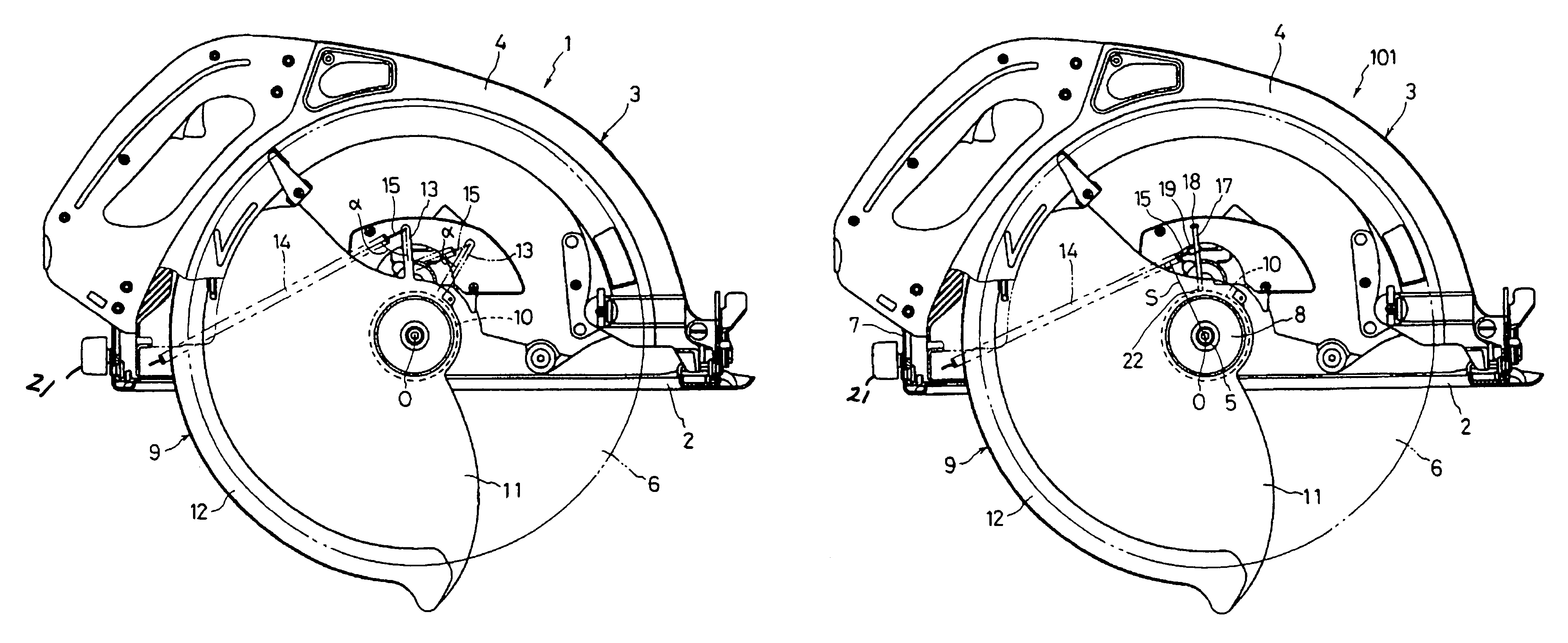
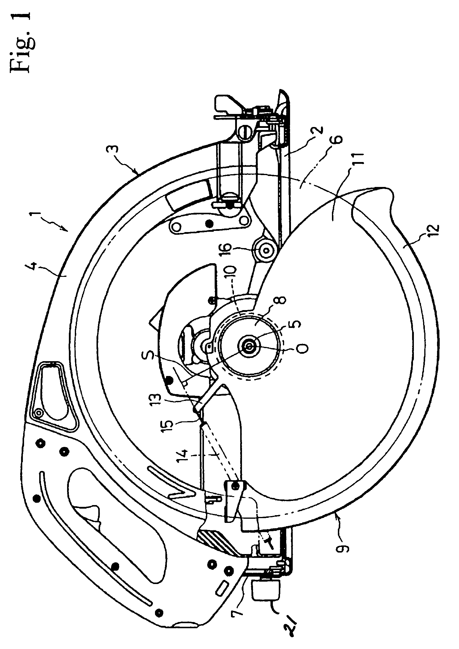
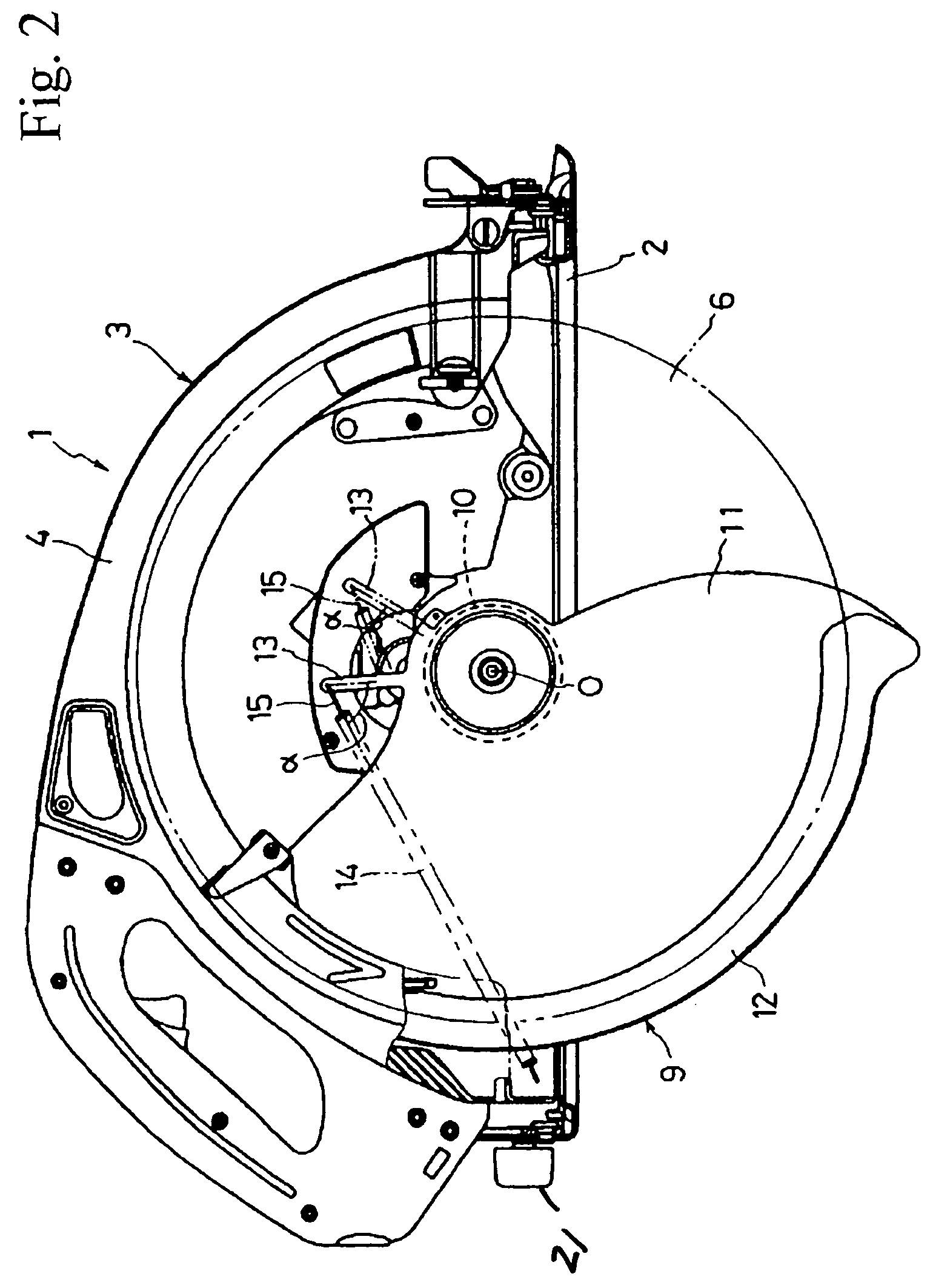
[0031]FIG. 1 is a front elevation of a circular saw 1 according to the present invention. The circular saw 1 includes a generally rectangular and flat base plate 2 and a saw blade assembly 3 mounted on the base plate 2. The saw blade assembly 3 encases a motor (not shown) on its back side and includes an upper blade guard 4 secured to its front side. A spindle 5 transmitting the rotation of the motor is supported by a bearing box 8 coupled to the saw blade assembly 3, projecting from the motor into the space defined by the upper blade guard 4. A circular saw blade 6 is attached at right angles to the top end of the spindle 5 such that approximately half of the blade protrudes below the base plate 2. Furthermore, the right end (as viewed in FIGS. 1–3, i.e., the front end in relation to the direction in which cutting is to be made) of the upper blade guard 4 is hinged to a shaft (not shown) in such a manner as to allow the saw blade assembly 3 to pivot on the shaft. The opposite end o...

second embodiment

[0037]An alternate structure of the present invention is described hereinafter with reference to the attached drawings, in particular FIGS. 4–6, in which identical or similar reference numerals or characters denote identical or similar parts or elements throughout the several views. Therefore, description of such elements is omitted.

[0038]With specific reference to FIG. 4, a circular saw 101 of this embodiment replaces the connecting bar 13 with a connecting bolt or pin 17 which is secured to the sleeve portion 10 of the lower blade guard 9 at a base or bottom end 22 of the bolt and projects upper-rearward along a diametrical line passing through the axis of rotation of the guard 9. The connecting bolt 17 has a head 18 having a larger diameter than the rod portion so as to prevent a ring 19 (to be described in further detail below) attached to the connector 15 from slipping off the bolt 17. Furthermore, the connecting bolt 17 has the same length as the connecting bar 13 described in...


PUM

PropertyMeasurementUnit
angleaaaaaaaaaa
angleaaaaaaaaaa
axis of rotationaaaaaaaaaa

Abstract

A circular saw (1) includes a base plate (2) and a saw blade assembly (3) including a lower blade guard (9) for covering a saw blade (6). The blade guard includes a sleeve portion (10) rotatably fitted on a bearing box (8) coupled to the saw blade assembly and a sectoral portion (11) extending radially from the sleeve portion in the rear of the blade. A connecting bar (13) projects radially rearward from the sectoral portion. A spring (14) is stretched between the top of the connecting bar (13) and a lower rear portion of an upper blade guard (4) close to the base plate. When not in use, torque, generated as the product of the spring's tensile force and the perpendicular distance (S) from the line of action or the force to the axis of rotation (O), rotates the blade guard to a closed position.

Description

[0001]This application claims priority on Japanese Patent Application No. 2001-130107 filed on Apr. 26, 2001, the contents of which are incorporated herein by reference.BACKGROUND OF THE INVENTION[0002]1. Field of the Invention[0003]The present invention generally relates to electric power tools. More particularly, the present invention relates to circular saws including a base plate, a saw blade assembly mounted on the base plate, and a lower blade guard for covering the lower portion of the saw blade.[0004]2. Description of the Related Art[0005]A typical circular saw includes a generally rectangular base plate and a saw blade assembly mounted on the base plate. The assembly in turn includes a motor-driven circular saw blade protruding below the base plate with the lower portion or teeth of the blade covered by a rotatable lower blade guard. Additionally, an extension spring is stretched between a portion of the blade guard decentered or displaced from the axis of its rotation and ...

Claims


Application Information

Patent Timeline
Patent Type & Authority Patents(United States)
IPC IPC(8): B27G19/04B23D45/16B27B9/00B23D47/00
CPCB27G19/04B27B9/00
Inventor HANEDA, KATSUJITSUCHIYA, SHINGONOGUCHI, HIROTAKA
Owner MAKITA CORP
Why Eureka
Try Eureka