Thermoelectrically heated/cooled cupholder system

Inactive Publication Date: 2006-08-15
CONTINO ROBIN L
View PDF16 Cites 111 Cited by
  • Summary
  • Abstract
  • Description
  • Claims
  • Application Information

AI Technical Summary

Benefits of technology

[0014]The cupholder member is formed as a number of sections that are cooperatively oriented to form a generally cylindrical shape. In order to allow for different cup sizes and profiles, the cupholder sections are mounted to the outer frame using a spring-loaded pin-in-groove system, such that the cupholder sections are free to slide to form a wider or narrower cylinder, or even to conform to conform to a non-cylindrical container (such as a cup having pitched sides), as needed. Each pin-in-groove is provided with a spring in order to maintain the cupholder member in the smallest circular profile allowed by

Problems solved by technology

One of the principal drawbacks related to keeping beverages at their proper serving temperature is the tendency for such beverages to assume the ambient temperature in the environment into which they have been placed.
A cold beverage, such as an iced soda, quickly warms to room temperature, causing the ice to melt and dilute the beverage.
These passive systems slow the process of heat transfer, but they do not eliminate it or compensate for it entirely.
One of the drawbacks of these designs is the orientation of the thermoelectric device—namely, at the bottom of the cup or cupholder.
First, in such an arrangement, the cup or the liquid can be reasonably guaranteed to be in physical contact with the thermoelectric device, which contact aids in the heat transfer as any air between the thermoelectric device and the cup or liquid acts as an insulator, reducing the efficiency.
Second, because at least for cooling operations it is necessary to place fins against the heat sink, the ability to place the fins appropriately affects the arrangement of the device members.
However, the plac

Method used


Image

  • Thermoelectrically heated/cooled cupholder system
  • Thermoelectrically heated/cooled cupholder system
  • Thermoelectrically heated/cooled cupholder system

Examples


Embodiment Construction

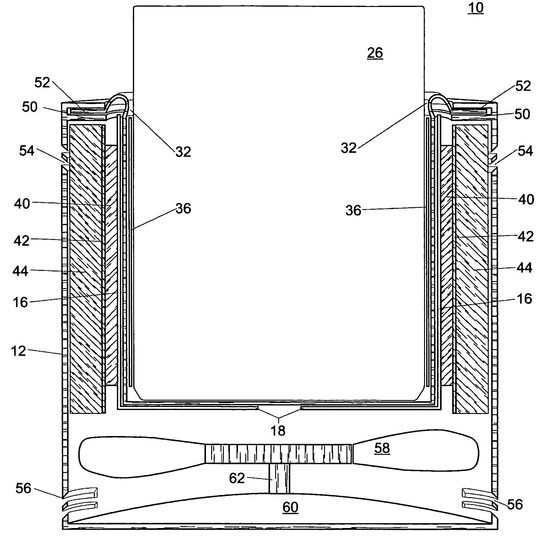
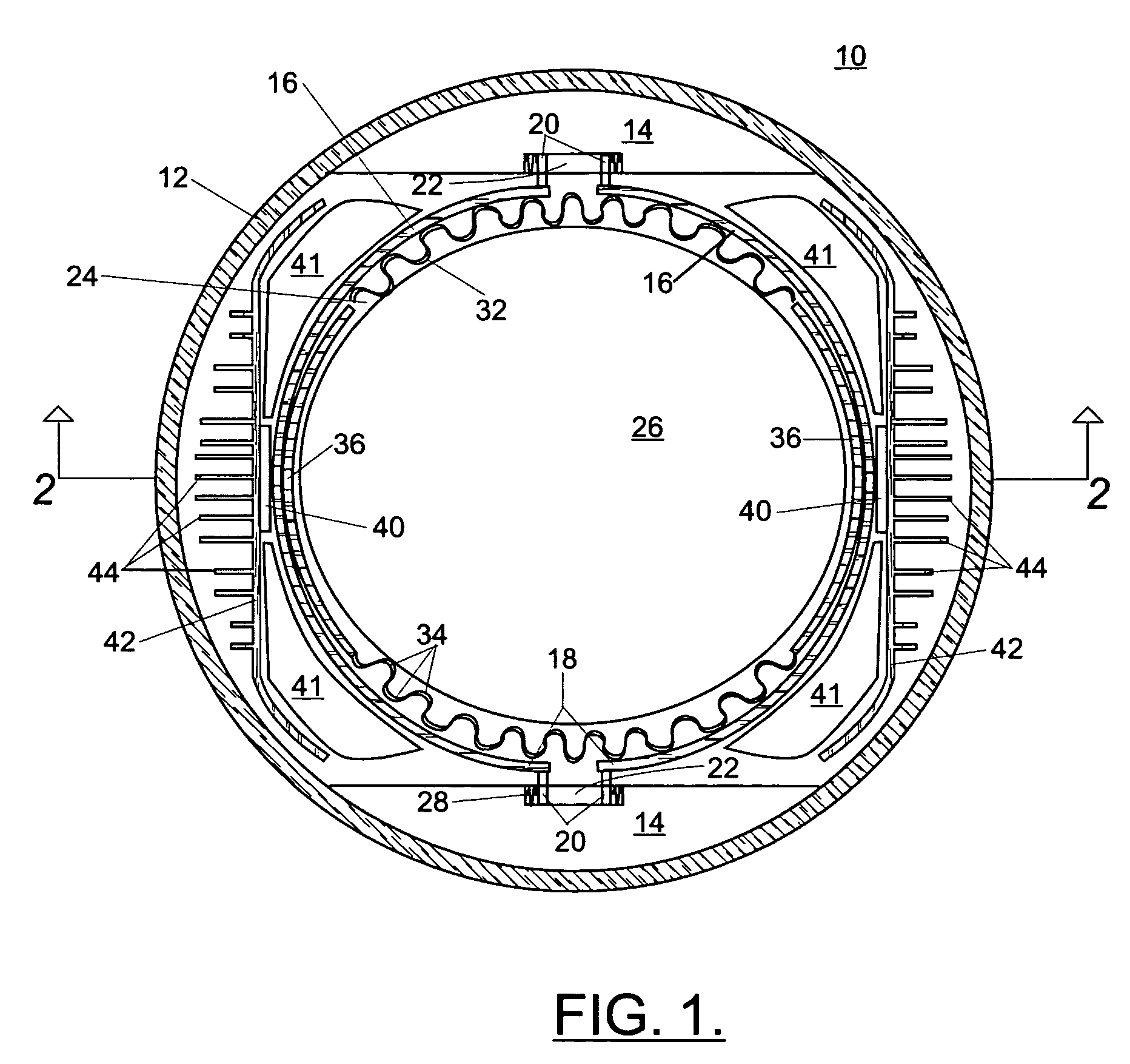
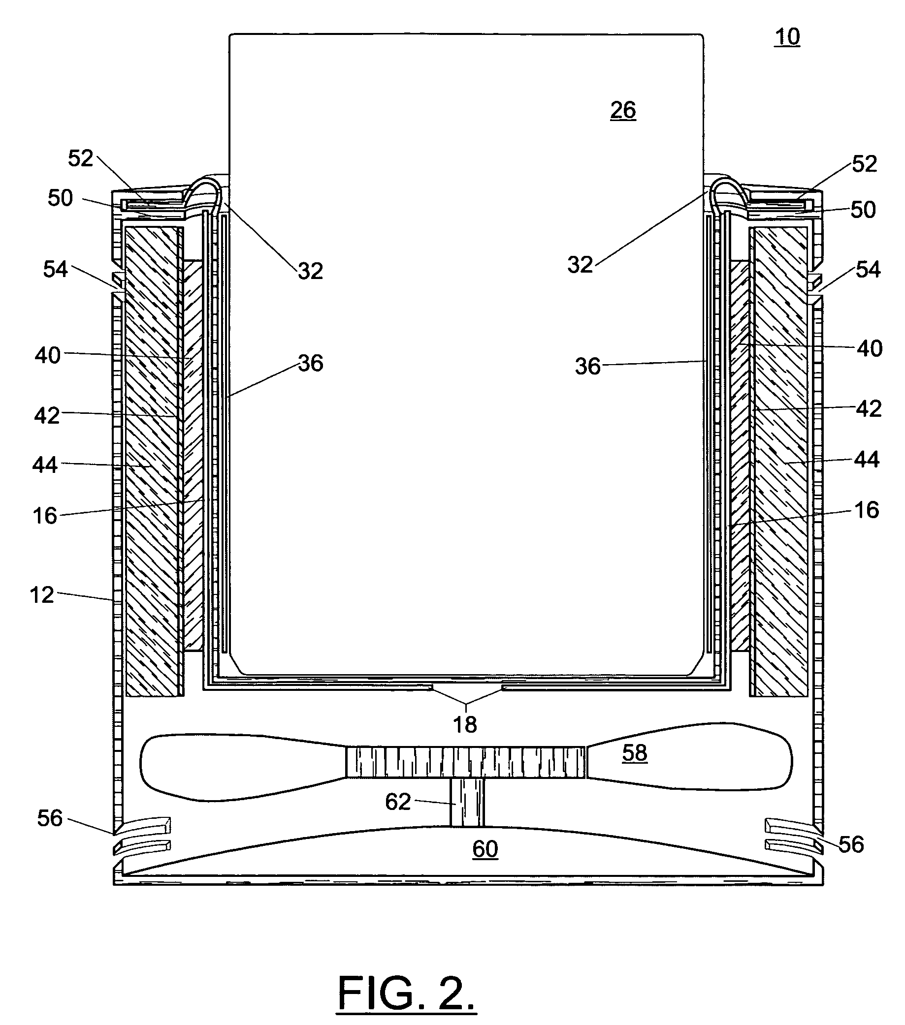
[0021]Referring now to the drawings, a thermoelectrically heated and cooled cupholder system 10 according to the present invention is shown in a plan view in partial cross-section in FIG. 1. Outer frame 12 is generally cup-shaped, i.e., generally cylindrical and open at the top thereof, and is ideally integrable with the console of an automobile (not shown), for instance. Outer frame 12 is ideally made of plastic or another similarly suitable material.

[0022]Outer frame 12 is provided on the interior thereof with a pair of mounting fixtures 14, which will be described in greater detail below in connection with an expansion feature of the invention. A pair of semi-cylindrical cupholder units 16 cooperate to form a generally cylindrical cupholder member 18. Cupholder member 18 is ideally made of a heat-conductive material such as aluminum or another metal suitable for conducting heat from or to substantially all of the surface area of cupholder member 18.

[0023]Each of the cupholder uni...


PUM


Abstract

A system for retaining and controlling the temperature of a beverage, suitable for installation in an automobile, includes a generally cylindrical, open-topped heat-conductive expandable cupholder, a heat-conductive liner, one or more thermoelectric devices located on a vertical exterior side of the cupholder, a heat sink contacting the thermoelectric device and thermally insulated from the cupholder; and a switch. The placement of the thermoelectric device and an improved arrangement for contact between the cupholder and the cup enable more efficient heat transfer.

Description

CROSS-REFERENCE TO RELATED APPLICATIONS[0001]This application claims the benefit of U.S. Provision Patent Application Ser. No. 60 / 496,530, filed Aug. 20, 2003, the entirety of which is incorporated herein by reference.FIELD OF THE INVENTION[0002]The present invention relates to a thermoelectrically heated and cooled cupholder system and more specifically to such a system wherein a finned Peltier device provides for heat transfer through efficient contact between the cup and the heat transfer surface.BACKGROUND OF THE INVENTION[0003]One of the principal drawbacks related to keeping beverages at their proper serving temperature is the tendency for such beverages to assume the ambient temperature in the environment into which they have been placed. A hot beverage, such as coffee or tea, particularly when served in an uninsulated cup, quickly cools. A cold beverage, such as an iced soda, quickly warms to room temperature, causing the ice to melt and dilute the beverage.[0004]Various sol...

Claims


Application Information

Patent Timeline
IPC IPC(8): F25B21/02
CPCB60H1/00264B60H1/00478B60N3/104B60N3/108F25D31/007F25B21/04F25D2331/809F25B2321/0251F25D21/04F25D2331/805
Inventor SCHAFER, CHRIS
Owner CONTINO ROBIN L
Why Eureka
Try Eureka