Resonator

a technology of resonators and pistons, applied in the field of resonators, can solve the problems of large parts number, complicated assembly work, and narrow engine room space, and achieve the effect of increasing/decreasing the number of passages

Inactive Publication Date: 2006-08-15
TOYODA GOSEI CO LTD
View PDF6 Cites 27 Cited by
  • Summary
  • Abstract
  • Description
  • Claims
  • Application Information

AI Technical Summary

Benefits of technology

[0020]Therefore, an object of the invention is to provide a resonator which can make a plurality of frequencies to be reduced in the sound-pressure level in suction noises and a plurality of own resonance frequencies correspond to each other.
[0069]According to the invention, it is possible to provide a resonator which can increase / decrease the number of passages for intake air in response to an engine speed.

Problems solved by technology

Therefore, the assembling works become complicated.
As a result, the limited space in the engine room is narrowed by the dual intake system.
Moreover, the large parts number complicates the structure.
Of the two intake passages of the dual intake system, therefore, one intake passage is excessive, only in case the engine speed is low.

Method used


Image

  • Resonator
  • Resonator
  • Resonator

Examples


first embodiment

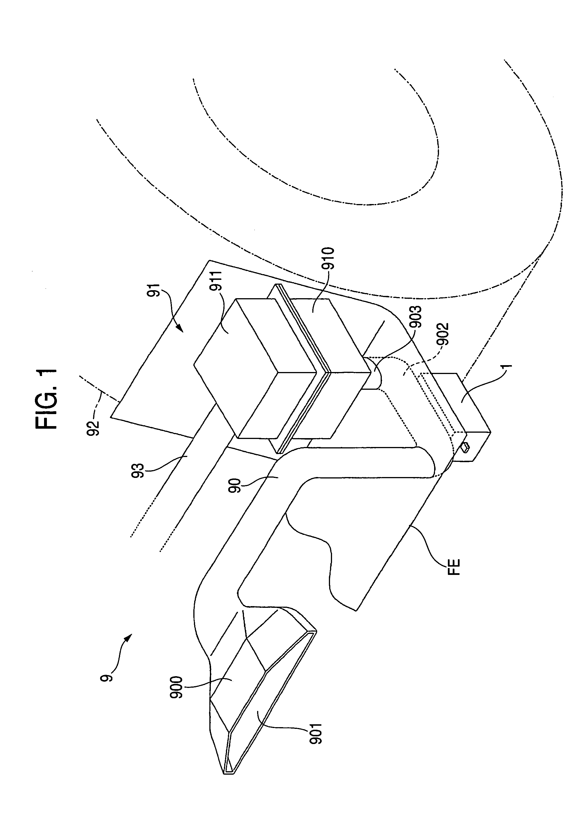
[0098]A first description is made on an intake system, in which a resonator of this embodiment is arranged. FIG. 1 is a perspective view of the intake system, in which the resonator of this embodiment is arranged. As shown in FIG. 1, an intake system 9 is provided with an intake duct 90, an air cleaner 91 and an air cleaner hose 93. An intake passage is defined in the intake system 9. The intake duct 90 and the air cleaner 91 are arranged in a space in front of front tires 92 (as indicated by single-dotted lines) of a vehicle.

[0099]The intake duct 90 is made of PP (Polypropylene) into a cylindrical shape. The intake duct 90 is included in an intake member of the invention. The intake duct 90 has its upstream side end portion 900 formed into a flattened trapezoidal shape. An intake port 901 is opened in the upstream side end portion 900. This upstream side end portion 900 is fastened on the (not-shown) radiator upper support. The intake duct 90 is curved into a U-shape. The U-shaped ...

second embodiment

[0123]This embodiment is different from the first embodiment in that a group of multiple pores is formed in place of the slit in the upper wall of the housing. Therefore, the following description is made exclusively on the difference.

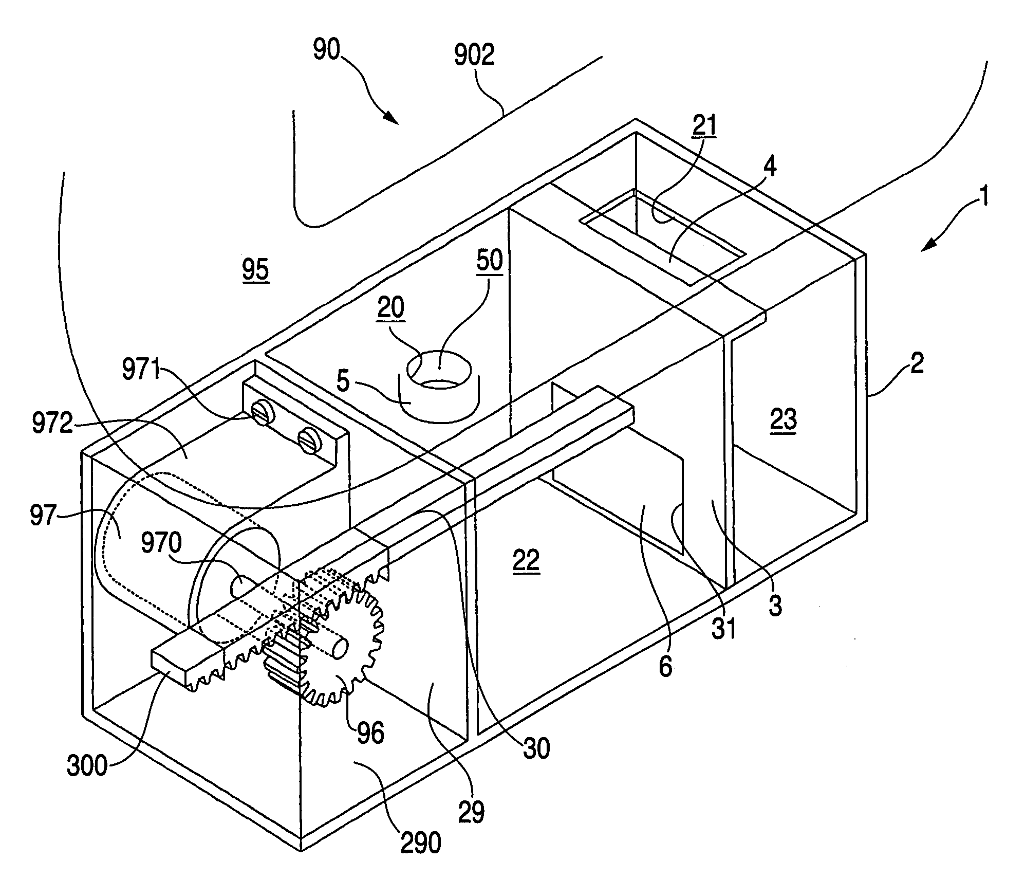
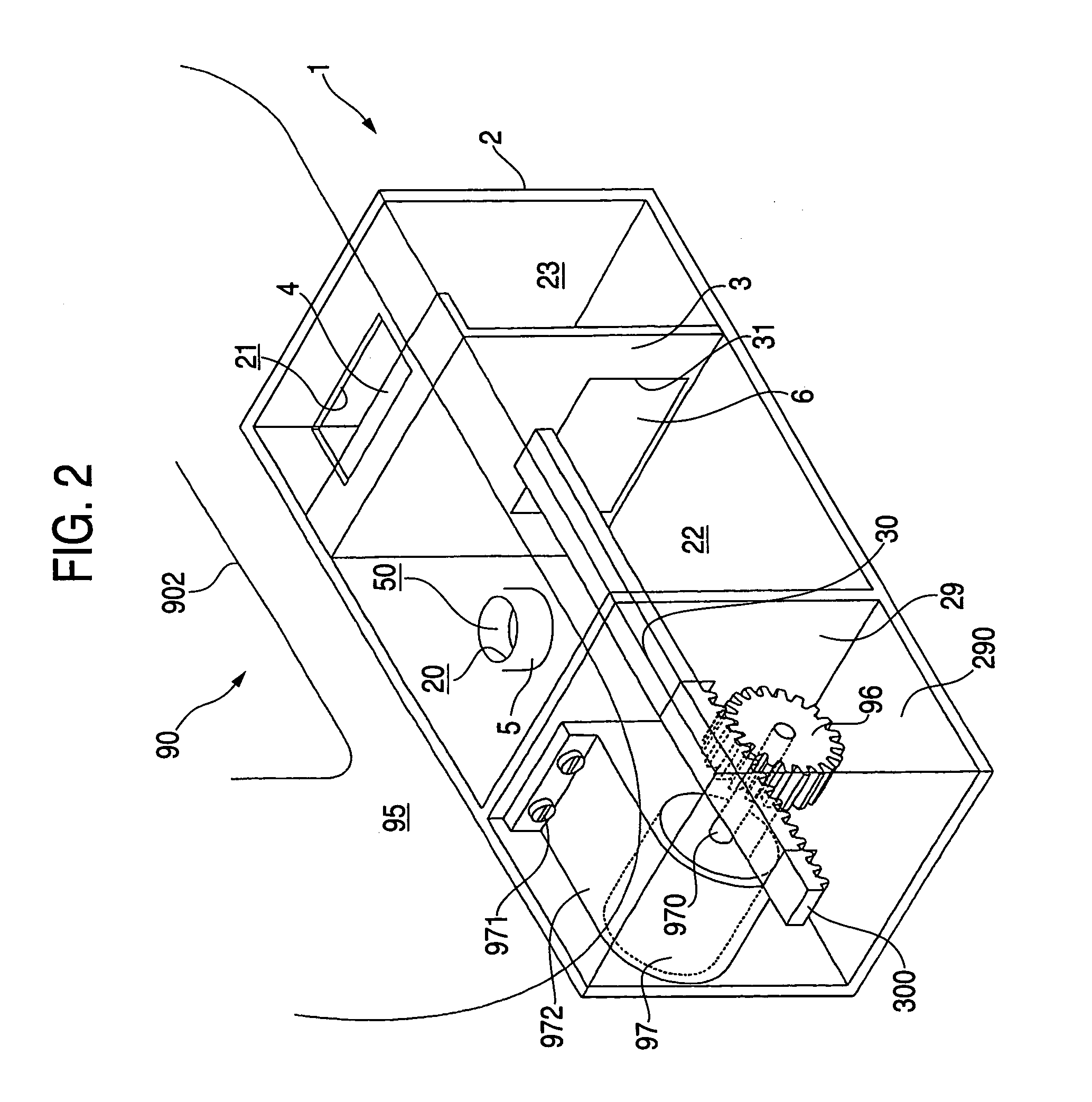
[0124]FIG. 5 is a transparent, perspective view of a resonator of this embodiment. Here, the portions corresponding to those of FIG. 2 are designated by the common reference numerals. As shown, small pores 240 are formed in the upper wall of the housing 2. These pores 240 provide communication between the intake passage 95 and the second volume portion 23. The multiple pores 240 make up a pore group 24. This pore group 24 is arranged widely with respect to the moving direction of the movable partition 3. The resonator 1 of this embodiment has actions and effects similar to those of the resonator of the first embodiment.

third embodiment

[0125]This embodiment is different from the first embodiment in that the movable partition and the movable cover are moved by the intake vacuum. Another difference resides in that the first volume portion and the second volume portion, and the first opening and the slit are individually arranged reversely with respect to the intake flow direction. Therefore, the description is made exclusively on the differences.

[0126]FIG. 6 is a transparent, perspective view of a resonator of this embodiment. Here, the portions corresponding to those of FIG. 2 are designated by the common reference numerals. The upper wall of the U-shaped bottom portion 902 of the intake duct 90 is recessed to form a differential pressure throttling portion 98. This differential pressure throttling portion 98 reduces the sectional area of the intake passage 95 locally.

[0127]In the upper wall of the housing 2, the first opening 20 is opened to confront the differential pressure throttling portion 98 vertically. The ...


PUM


Abstract

A resonator comprises a housing arranged in an intake member for defining an opening to communicate with an intake passage and a volume portion to communicate with the opening portion, a movable partition which can change the volume of the volume portion, and a movable cover associated with the movable partition for changing the opening area of the opening portion.

Description

[0001]This application is based on Japanese Patent Application Nos. 2004-100271 and 2004-100299, which are incorporated herein by reference.BACKGROUND OF THE INVENTION[0002]1. Field of the Invention[0003]The present invention relates to a resonator for suppressing intake noises.[0004]2. Description of the Related Art[0005]A Helmholtz type resonator is provided with a cylindrical member and a housing. The cylindrical member is branched and connected at its one end to an intake duct. This intake duct is defined into an intake passage. This intake passage is opened at its cylindrical member connecting portion to form an opening. The housing is connected to the other end of the cylindrical member. The inside of the housing is defined into a volume portion.[0006]Here, the resonance frequency f of the resonator can be obtained for a sound velocity C, an opening area S of the opening, a length L of the cylindrical member and a volume V of the volume portion from the following Formula:[0007...

Claims


Application Information

Patent Timeline
Patent Type & Authority Patents(United States)
IPC IPC(8): F02M35/10F02M35/12
CPCF02M35/1261F02M35/1222
Inventor KINO, HITOSHIOGASAWARA, YUTAKA
Owner TOYODA GOSEI CO LTD
Why Eureka
Try Eureka