Heat recovery ventilator

a ventilator and heat recovery technology, applied in the field of air exchange ventilators, can solve the problems of heat recovery ventilators, cost and complexity of utilizing two actuators each controlling separate valves or flaps, and presents its own problems

Inactive Publication Date: 2006-08-15
TRENT METALS 2012
View PDF9 Cites 30 Cited by
  • Summary
  • Abstract
  • Description
  • Claims
  • Application Information

AI Technical Summary

Problems solved by technology

A problem occurs with heat recovery ventilators in situations where the fresh supply air is at below freezing temperatures.
A drawback to this arrangement is the cost and complexity associated with utilizing two actuators each controlling separate valves or flaps.
While this does eliminate a valve or flap and an actuator it does present its own problems.
As the actuator and flaps are disposed adjacent the cold supply there is a possibility of their freezing, thereby rendering them inoperable.

Method used


Image

  • Heat recovery ventilator
  • Heat recovery ventilator
  • Heat recovery ventilator

Examples


Embodiment Construction

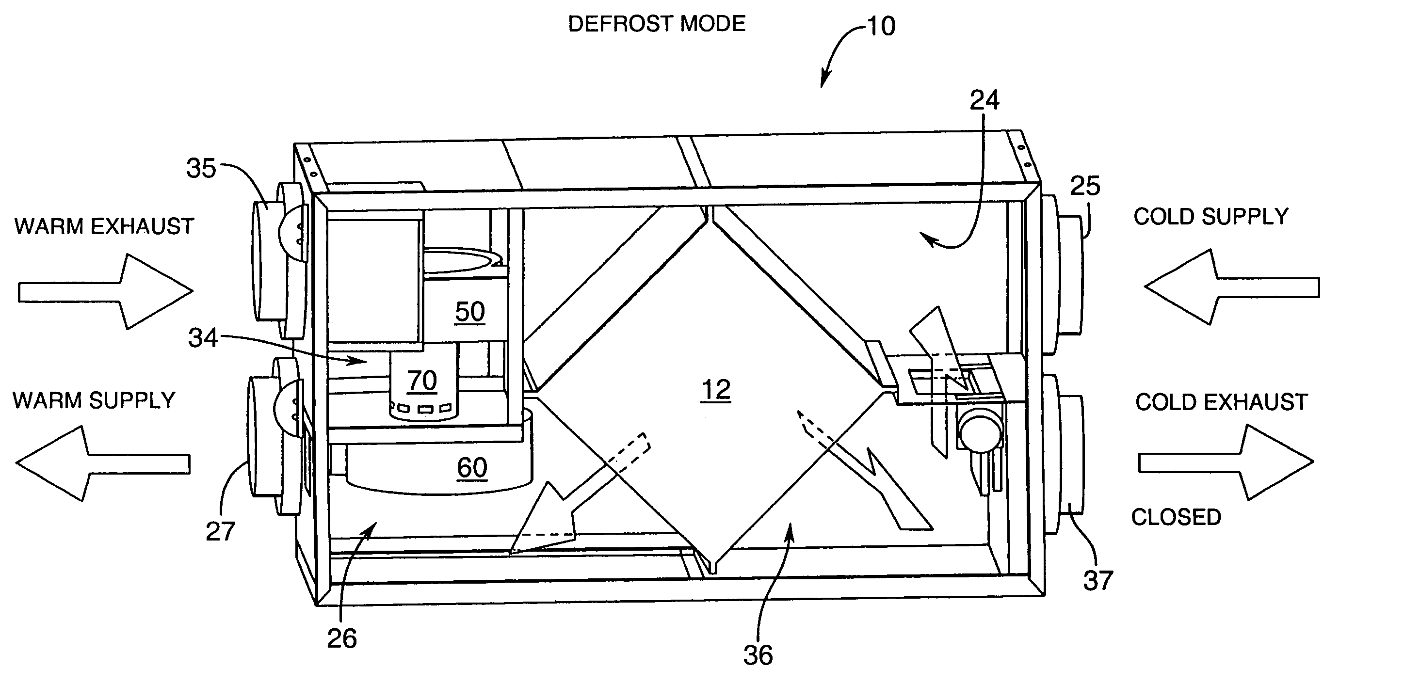
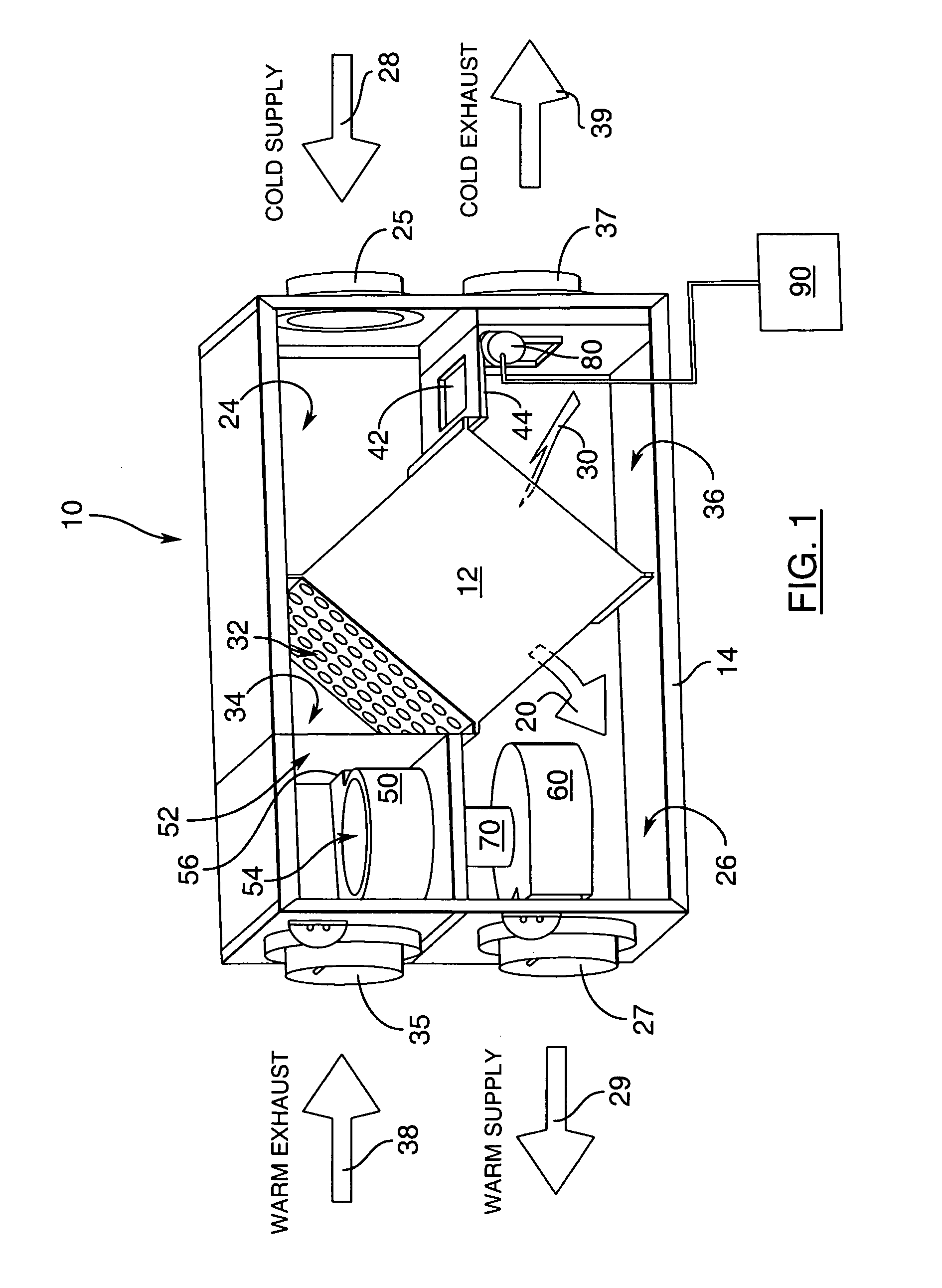
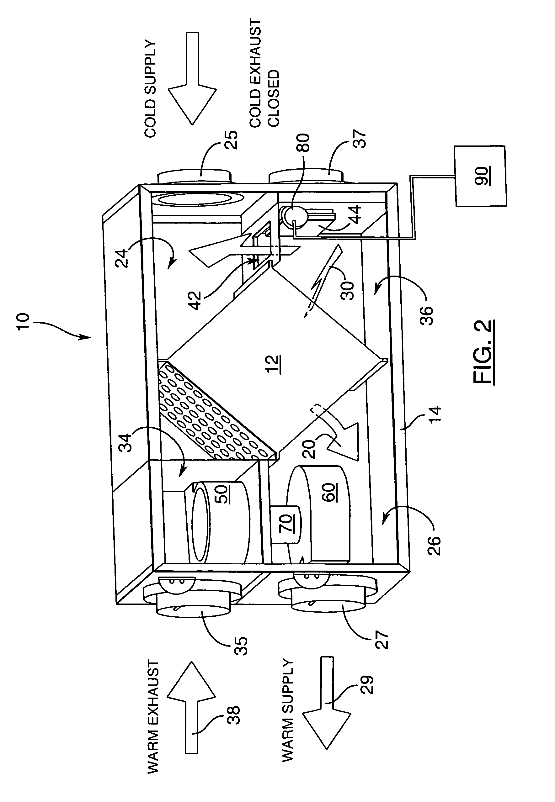
[0022]A heat recovery ventilator according to the present invention is generally indicated by reference 10 in the accompanying illustrations. At the core of the heat recovery ventilator 10 is a heat exchanger 12 having an inlet passageway schematically illustrated by arrow 20 and an exhaust passageway schematically illustrated by arrow 30. A housing 14 defines an exterior of the heat recovery ventilator 10. It will be appreciated that the actual unit will have a front cover which is not shown in FIGS. 1 and 2 to show its interior.

[0023]The inlet passageway 20 and exhaust passageway 30 are “discrete” in that they allow heat transfer between respective fluids flowing therealong without allowing commingling of the fluids. As is common with air to air heat exchangers, at least one of the inlet passageway 20 and exhaust passageway 30 may comprise a plurality of individual passageways, such as shown at reference 32. This maximizes the surface area to enhance heat transfer.

[0024]The inlet ...


PUM


Abstract

A heat recovery ventilator is provided which includes a heat exchanger having discrete inlet and exhaust passageways extending therethrough for providing heat transfer between respective fluids flowing along the inlet and the exhaust passages. The inlet passageway provides fluid communication between a supply inlet plenum and a supply discharge plenum. The outlet passageway provides fluid communication between an exhaust inlet plenum and an exhaust discharge plenum. The supply inlet plenum has a supply port for admitting supply air into the supply inlet plenum. The exhaust discharge plenum has an exhaust port for discharging air from the exhaust discharge plenum. A transfer port extends between the supply inlet plenum and the exhaust discharge plenum for providing fluid communication therebetween. A flow diverter is associated with the transfer port and is movable between a venting configuration closing the transfer port to allow fluid flow through the exhaust discharge port and a defrost configuration closing the exhaust discharge port to open the transfer port.

Description

FIELD OF THE INVENTION[0001]This invention relates to air exchange ventilators for admitting fresh air into an enclosure while exhausting stale air. More particularly, this invention relates to such ventilators which include a heat exchanger to extract heat from the stale air and transfer it to the fresh air. Still more particularly, this invention relates to defrost arrangements for such ventilators.BACKGROUND OF THE INVENTION[0002]Highly energy efficient buildings are generally designed to avoid uncontrolled ingress or egress of air. As some air exchange is necessary to remove stale air and replace it with fresh air, it is desirable to first remove heat from the stale air to avoid losing the heat with the air. A heat recovery ventilator is used for this purpose.[0003]A heat recovery ventilator includes a heat exchanger with two discrete air passageways, one for stale air exhaust and the other for fresh supply air. As the exhaust air passes out of the enclosure through the heat exc...

Claims


Application Information

Patent Timeline
Patent Type & Authority Patents(United States)
IPC IPC(8): F28F27/02F24F12/00
CPCF24F12/006Y02B30/563Y02B30/56
Inventor TAYLOR, WAYNE
Owner TRENT METALS 2012
Why Eureka
Try Eureka