Low power wireless display tag systems and methods

a low-power, wireless display technology, applied in the field of electronic inventory systems, can solve the problems of limiting the usability of rfid devices, undesirable parasitic losses, power consumption of transceivers, etc., and achieve the effect of low-power operation of rfid

Active Publication Date: 2006-08-15
AGILE DISPLAYS LLC
View PDF22 Cites 45 Cited by
  • Summary
  • Abstract
  • Description
  • Claims
  • Application Information

AI Technical Summary

Benefits of technology

[0011]The present invention provides a plurality of techniques and systems which optimize low power operation of RFID devices, thereby overcoming many of the limitations of the prior art and enabling the cost-effection production and implementation of a low-profile Wireless Display Tag (WDT) that fits within the confines of shelf-edge C-channel on a retail store display shelf, or, alternatively, can be used as a hang tag for other items.
[0013]In addition, the present invention provides for sharing of high-power-consumption devices across multiple WDTs, thereby significantly reducing power consumption and cost since such devices typically represent significant costs as well as high power consumption.
[0014]Further, the present invention provides for low power, low cost repeaters which may be strategically placed in locations requiring WDTs to be read. Such repeaters typically will pick up weak uplink signals from the WDT devices, and then boost and retransmit those signals to either the host system, either directly or through intermediate devices such as access points.
[0015]In addition, a power amplifier may be provided which is driven with the absolute value of the input waveform, thus minimizing power waste and avoiding detrimental parasistic effects. In at least some implementations of such techniques, the frequency of the power amplifier can be reduced, for example halved, to provide further power reduction.

Problems solved by technology

However, the power requirements and limited range for typical prior art electronic shelf labels have led to serious shortcomings.
In addition, such shortcomings have made it necessary to situate costly readers proximate to the tags, leading to costly networks which significantly limit the usability of RFID devices.
In part, these shortcomings are associated with the power consumption of the transceiver contained within many such devices.
In such arrangements, the waveform energy between the negative peak of the input waveform and the turn-on voltage of the active device is not only wasted, but can lead to undesirable parasitic losses.

Method used


Image

  • Low power wireless display tag systems and methods
  • Low power wireless display tag systems and methods
  • Low power wireless display tag systems and methods

Examples


Embodiment Construction

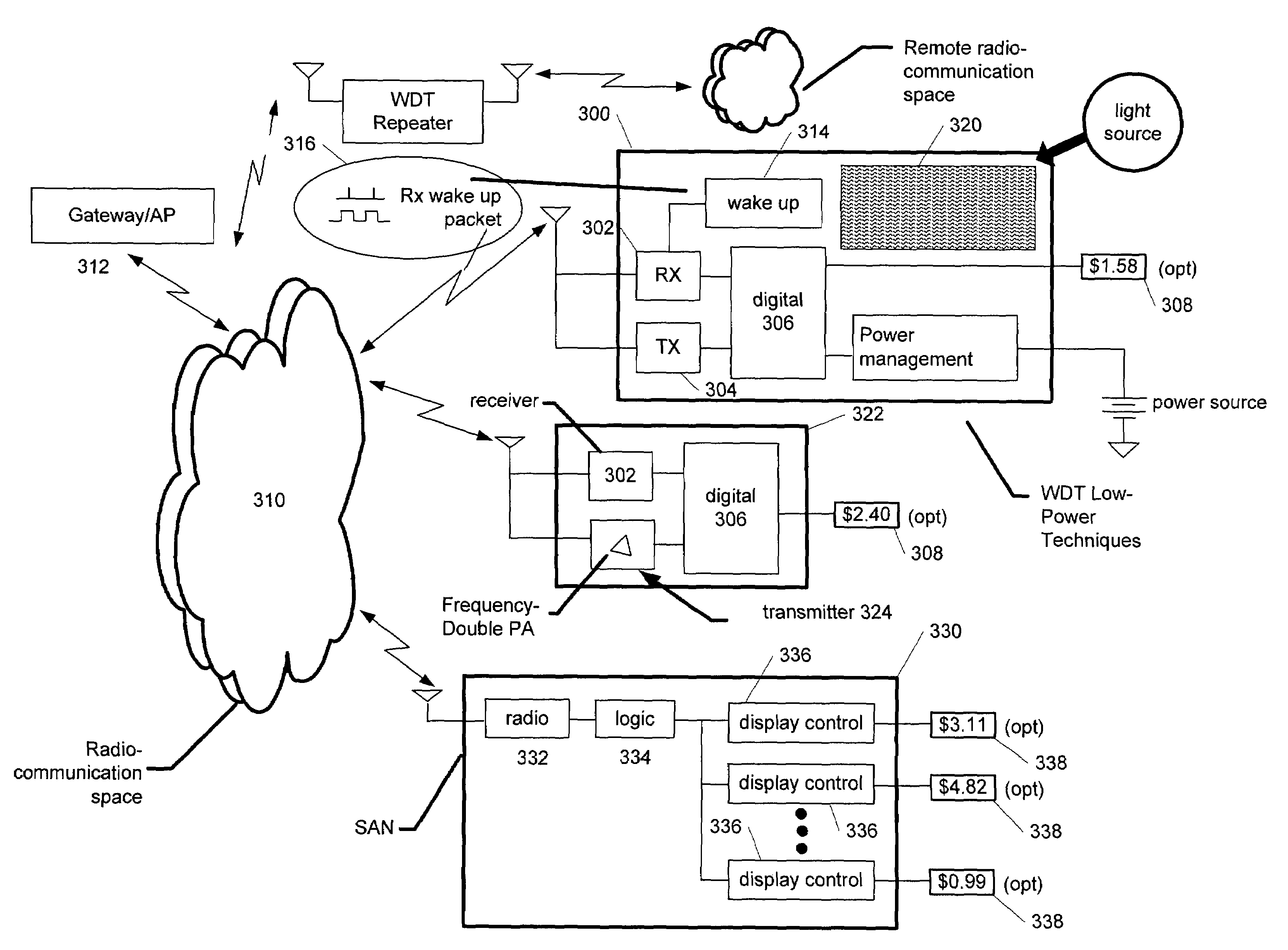
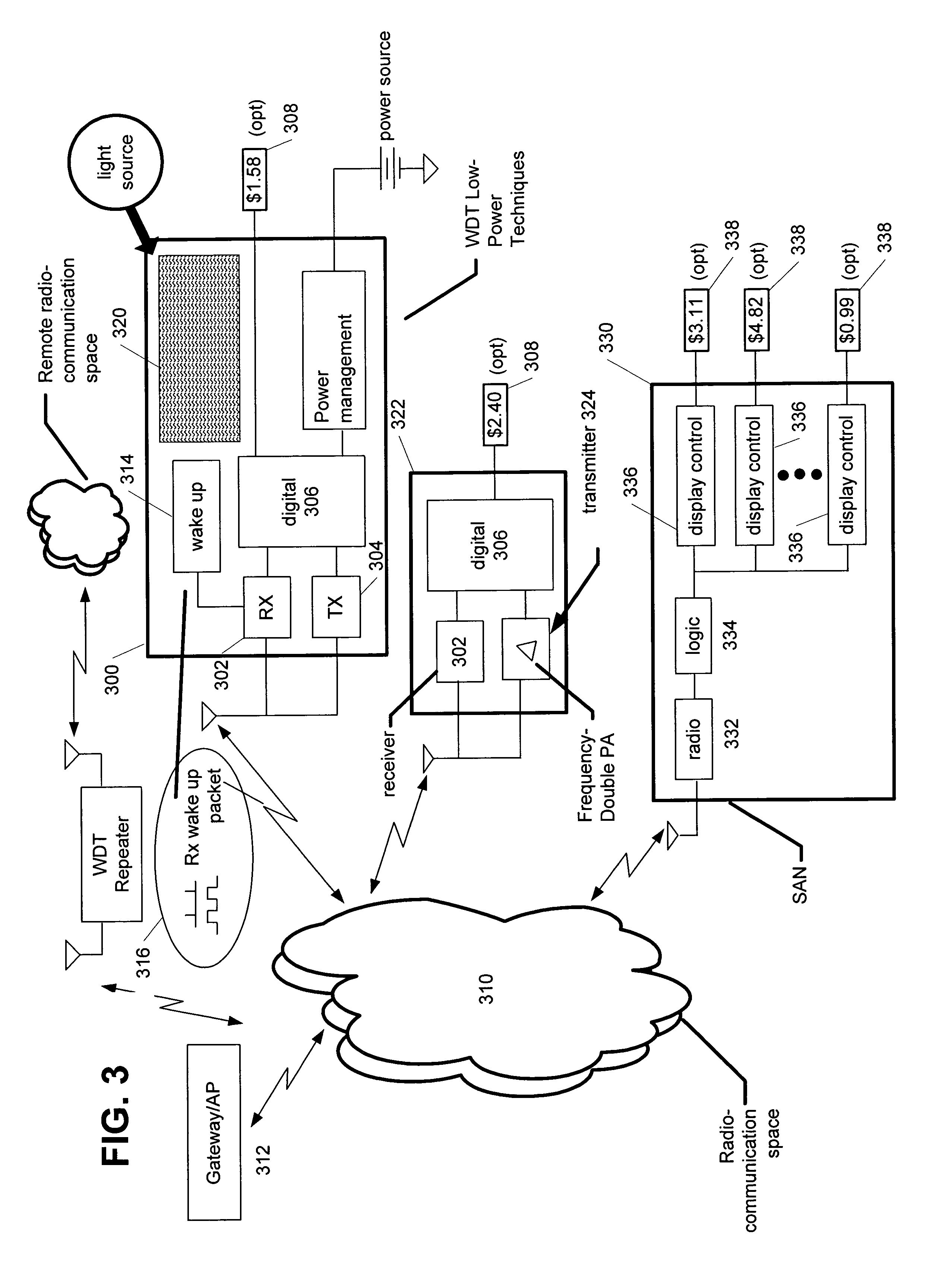
[0030]Referring first to FIG. 3, a system in accordance with the present invention is illustrated. In particular, numerous aspects of the present invention are illustrated in a robust exemplary implementation, although it will be appreciated by those skilled in the art that not all of these aspects of the inventions are necessarily included in every implementation. A wireless display tag (WDT) 300 comprises a receiver 302 and transmitter 304, which may be integrated as a transceiver in at least some embodiments. Digital logic 306 handles communications and also manages the functions of the WDT, as described in the related applications, including driving a display 308. In a typical arrangement, the communications between the WDT and an associated host [not shown] are wireless and occur through radio space 310. The communications with the host may be received by a gateway or other access point 312. The WDT 300 may also include wake up circuitry 314, which responds to an appropriate in...


PUM


Abstract

A low-power system for use with Wireless Display Tags (WDTs) includes, in one or more exemplary arrangements, various power management techniques, including receiver wake-up, RF logic sharing, RF repeaters and a frequency doubling power amplifier which operates on the absolute value of the input signal.

Description

RELATED APPLICATIONS[0001]The present invention is related to the following co-pending applications filed concurrently herewith, assigned to the same assignee as the present invention, and incorporated herein by reference in full: U.S. patent application Ser. No. 11 / 019,660, entitled “An Error Free Method for Wireless Display Tag Initialization,”; U.S. patent application Ser. No. 11 / 019,978, entitled “Wireless Display Tag Unit,” U.S. patent application Ser. No. 11 / 019,976, entitled “Wireless Display Tag (WDT) Using Active and Backscatter Transceivers,” U.S. patent application Ser. No. 11 / 019,494, entitled “RE Backscatter Transmission with Zero DC Power Consumption,” and U.S. patent application Ser. No. 11 / 019,916, entitled “Multiuser Wireless Display Tag Infrastructure and Methods,”. Applicants further claim the benefit of and incorporate by reference in full the following, all filed on Dec. 18, 2003: U.S. patent application Ser. No. 60 / 530,819, entitled “Wireless Display Tag (WDT) ...

Claims


Application Information

Patent Timeline
Patent Type & Authority Patents(United States)
IPC IPC(8): G06K15/00G06K19/07
CPCG06K19/0701G06K19/07703G06K19/0723G06K19/0715
Inventor GOEL, ANURAGSAXENA, SUNITMCDONALD, MARK DOUGLASSAXENA, ASHWIN
Owner AGILE DISPLAYS LLC
Why Eureka
Try Eureka