

Magnetic staple remover
- Summary
- Abstract
- Description
- Claims
- Application Information
AI Technical Summary
Benefits of technology
Problems solved by technology
Method used
Image

Examples
Embodiment Construction
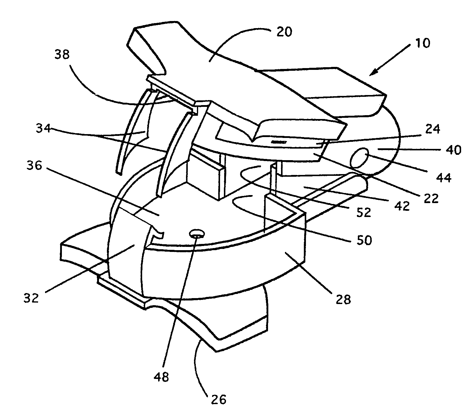
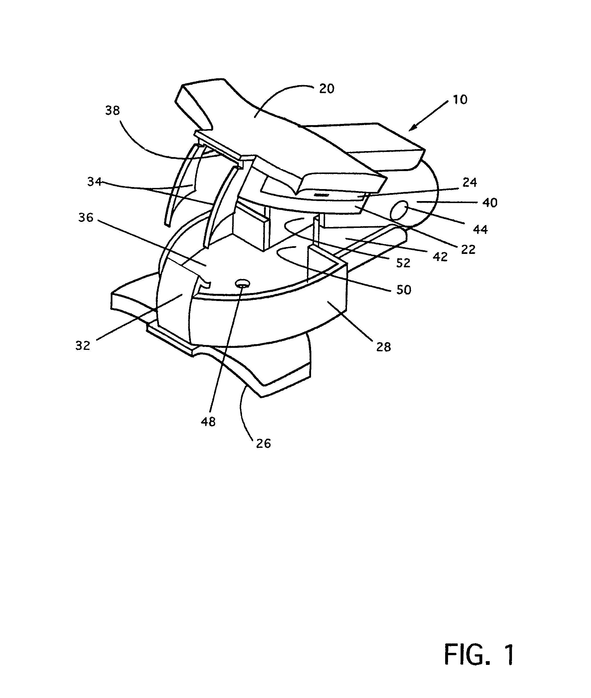
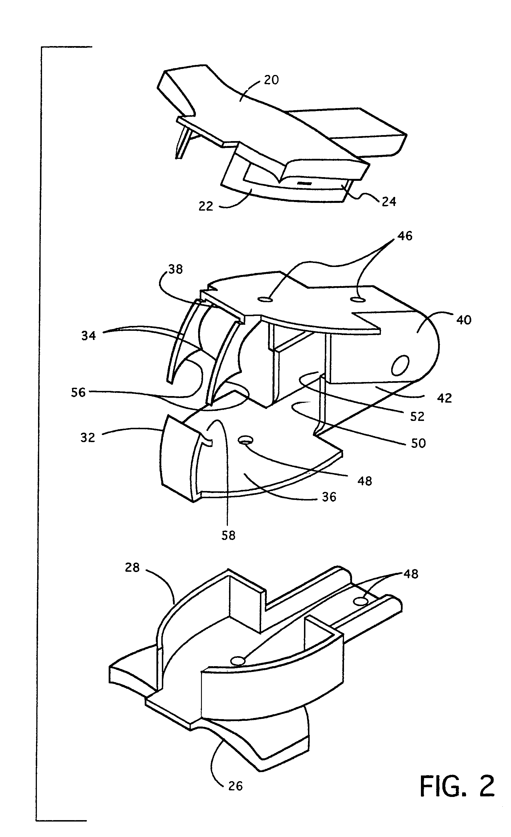
[0061]The staple remover of the present invention is illustrated in FIGS. 1–7. FIG. 1 is a perspective view of the subject invention generally identified at 10. FIG. 2 is an exploded view (shown as a bracketed view) of the subject invention 10 for more clarity and ease of description. The inventive staple remover 10 is illustrated as comprising a pair of cooperating arms, 40 and 42. More specifically, these arms include a larger arm 40 and a smaller arm 42, having working ends in the form of a pair of staple pulling prongs 34 (part of arm 40) defining a space therebetween as shown in FIG. 1, and a single staple pulling prong 32 (part of arm 42) having a single engaging edge sized to extend across said space between the pair of prongs 34.
[0062]Larger arm 40 is fabricated such that side walls thereof define channel section 52, and such that an upper surface plate portion 38 thereof (as viewed in FIG. 1) defines a top of large box 22 for collection of removed staples, as will be furthe...
PUM
 Abstract
Description
Claims
Application Information