
Three-wheel vehicle with swinging mechanism

Inactive Publication Date: 2006-08-15
HONDA MOTOR CO LTD
View PDF12 Cites 32 Cited by
  • Summary
  • Abstract
  • Description
  • Claims
  • Application Information

AI Technical Summary

Benefits of technology

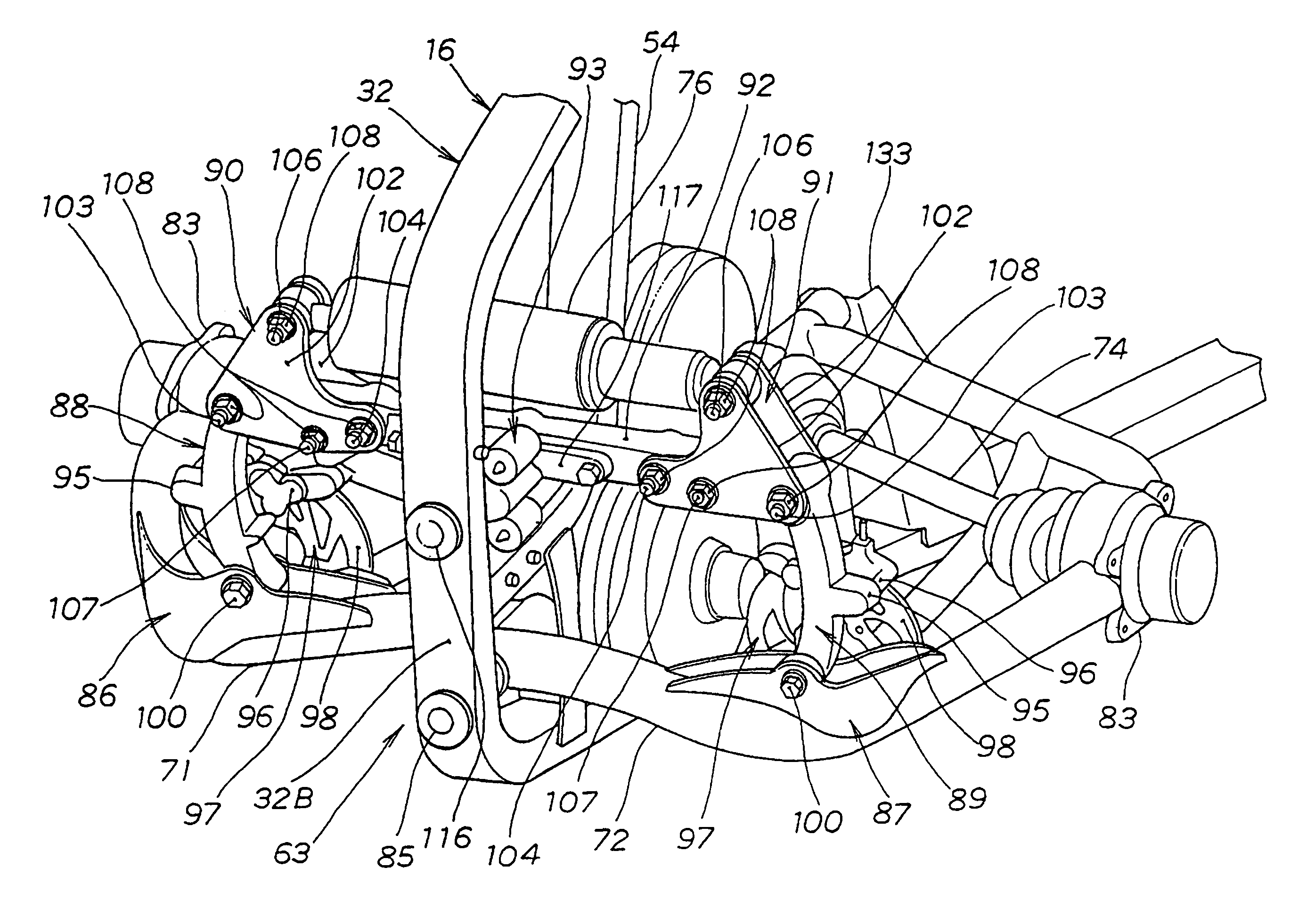
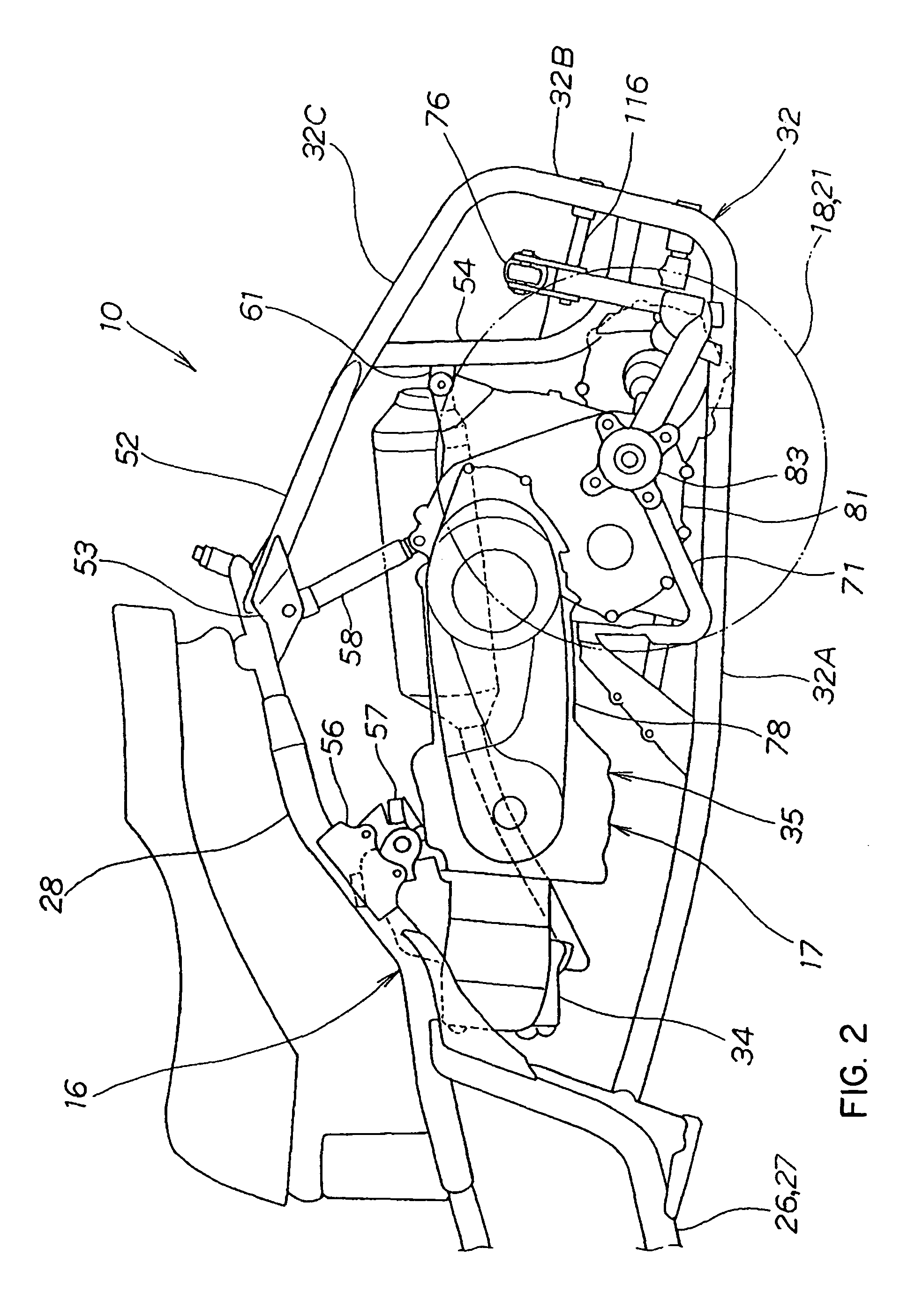
[0016]In one aspect of the present invention, a three-wheel vehicle provided with a swinging mechanism in which right and left rear wheels are attached to the right and the left of a body frame via suspension arms so that the rear wheels can be vertically moved and the swinging mechanism for allowing the lateral swing of the body frame for the side of the suspension arm is provided between the side of the suspension arm and the side of the body frame. A spindle extended in a longitudinal direction of the body is attached to the body frame. The right and left suspension arms are independently attached to the spindle so that the suspension arms can be vertically swung and the spindle also functions as a swinging shaft for swinging the body frame.
[0017]Each rear wheel can be independently vertically moved without lateral interference by supporting the right and left rear wheels by the spindle via the suspension arms mutually independent, compared with the conventional type in which the right and left rear wheels are coupled via an axle, for example. The ability of the right and left rear wheels to follow a road surface is increased, the roll of the body can be reduced and its ride comfort can be enhanced.
[0018]As the right and left suspension arms are attached to the same spindle, the number of parts can be reduced, compared with a case that right and left suspension arms are attached to separate swinging shafts. Thus, the cost can also be reduced.
[0019]Further, as the spindle also functions as a swinging shaft, the number of parts can be reduced, compared with a case that a spindle and a swinging shaft are separately provided, further reducing costs.
[0020]In another aspect of the present invention, a suspension arm is an A-type arm. As the suspension arm is A-type, the rigidity of the suspension arm can be enhanced and stability during operation can be enhanced.

Problems solved by technology

When such a swinging shaft is provided, the number of parts is increased and the cost is increased.
However, since the swinging shafts are provided to the right and the left, the cost is increased.

Method used


Image

  • Three-wheel vehicle with swinging mechanism
  • Three-wheel vehicle with swinging mechanism
  • Three-wheel vehicle with swinging mechanism

Examples


Embodiment Construction

[0041]As used herein, the term “coupled” means any structure or method that may be used to provide connectivity between two or more elements, which may or may not include a direct physical connection between the elements.

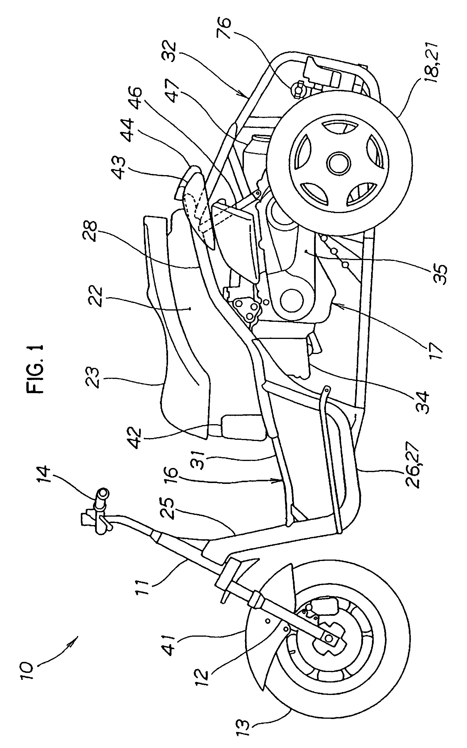
[0042]An embodiment of the invention will be described based upon attached drawings below. FIG. 1 is a side view showing a three-wheel vehicle provided with a swinging mechanism according to the invention. The three-wheel vehicle provided with the swinging mechanism 10 (hereinafter called the three-wheel vehicle 10) is composed of a front fork 12 steerably attached to a head pipe 11 via a steering shaft (not shown), a front wheel 13 attached to the lower end of the front fork 12, a handlebar 14 integrated with the front fork 12, a body frame 16 attached to the rear of the head pipe 11, a power unit 17 attached to the rear of the body frame 16, right and left rear wheels 21, 18 driven by the power unit 17, a housing box 22 attached to an upper part of the body frame ...


PUM


Abstract

In a three-wheel vehicle, right and left suspension arms are independently attached to a front swinging shaft and a rear swinging shaft so that the suspension arms can swing vertically, and the front swinging shaft and the rear swinging shaft function as a swinging shaft for swinging the body frame. A swinging mechanism is provided to restrict lateral rotation of the body frame.

Description

BACKGROUND OF THE INVENTION[0001]1. Field of the Invention[0002]The present invention relates to a three-wheel vehicle provided with a swinging mechanism, which reduces costs and enhances ride comfort.[0003]2. Description of the Related Art[0004]A three-wheel vehicle provided with a swinging mechanism in which right and left rear wheels are coupled via a shaft is known. For example, Japanese published examined patent application No. Sho58-24310 discloses such a vehicle. FIG. 19 is a side view showing a conventional type three-wheel vehicle (such as shown in Japanese published examined patent application No. Sho58-24310) provided with a swinging mechanism. A front frame 202 provided with one front wheel 201 and a rear frame 205 provided with right and left rear wheels 203, 204 are coupled via a pivot coupling device 206.[0005]The pivot coupling device 206 is composed of a housing attached to the front frame 202 and a pivot the front of which is rotatably attached to the housing and t...

Claims


Application Information

Patent Timeline
IPC IPC(8): B60G21/05B60G3/20B60G11/22B60G11/23B60G21/00B62D9/02B62K5/02B62K25/02
CPCB60G21/007B62K5/10B62D9/02B62K5/027B60G2204/421B60G2204/82B60G2204/8302B60G2300/45B60G2800/0194B60G2300/122
Inventor TAKAYANAGI, SHINJIMAKUTA, YOHEIKOBAYASHI, HIROYOSHI
Owner HONDA MOTOR CO LTD
Learn More