Stacked assembly of roofing caps

a technology of roofing caps and stacked assemblies, which is applied in the direction of transportation and packaging, washing machines, manufacturing tools, etc., can solve the problems of heavy weight of conventional cap feeding devices, time-consuming and inefficient manual placement of caps, and serious safety hazards for operators

Inactive Publication Date: 2006-08-15
PNEUTOOLS
View PDF52 Cites 68 Cited by
  • Summary
  • Abstract
  • Description
  • Claims
  • Application Information

AI Technical Summary

Benefits of technology

[0012]This invention provides a compact, light-weight cap feeding device that overcomes the problems associated with conventional nail guns and cap feeding devices.

Problems solved by technology

The manual placement of caps presents a serious safety hazard to the operator because the operator's hand is close to the nose of the gun when a nail is driven through the nose of the gun.
In addition, manual placement of caps is time-consuming and inefficient.
For example, conventional cap feeding devices are generally heavy, putting additional stress on the operator's hand holding the nail gun.
Also, many conventional cap feeding devices can only be installed close to the front end of a nail gun, making the nail gun not only heavy but also unbalanced with most of the weight placed at the front end of the gun.
This makes the nail gun difficult to handle and may put stress on the operator's hand and wrist.
In addition, with so many components placed near the nose of the gun, it is difficult to see the position of the nose of the gun, making a precise placement of a nail difficult.

Method used


Image

  • Stacked assembly of roofing caps
  • Stacked assembly of roofing caps
  • Stacked assembly of roofing caps

Examples


Embodiment Construction

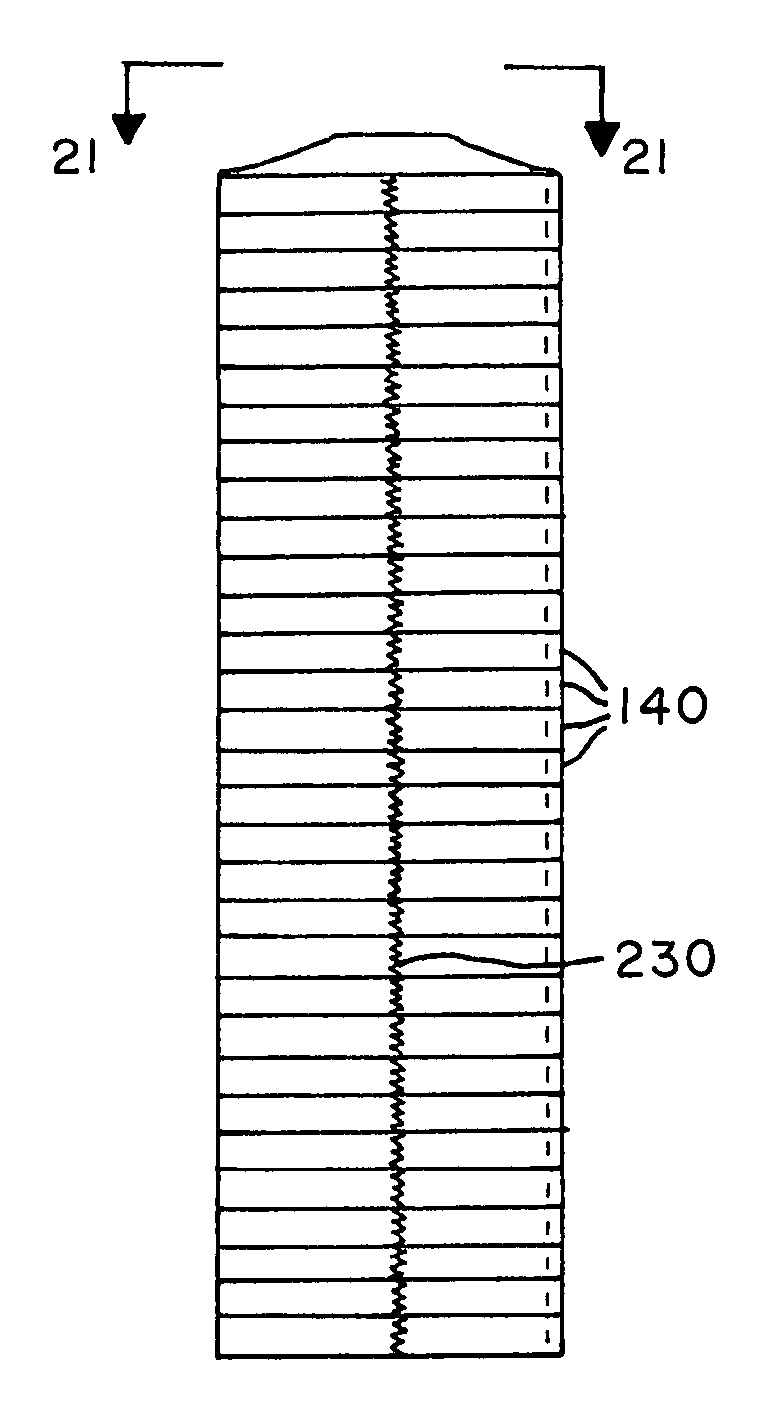
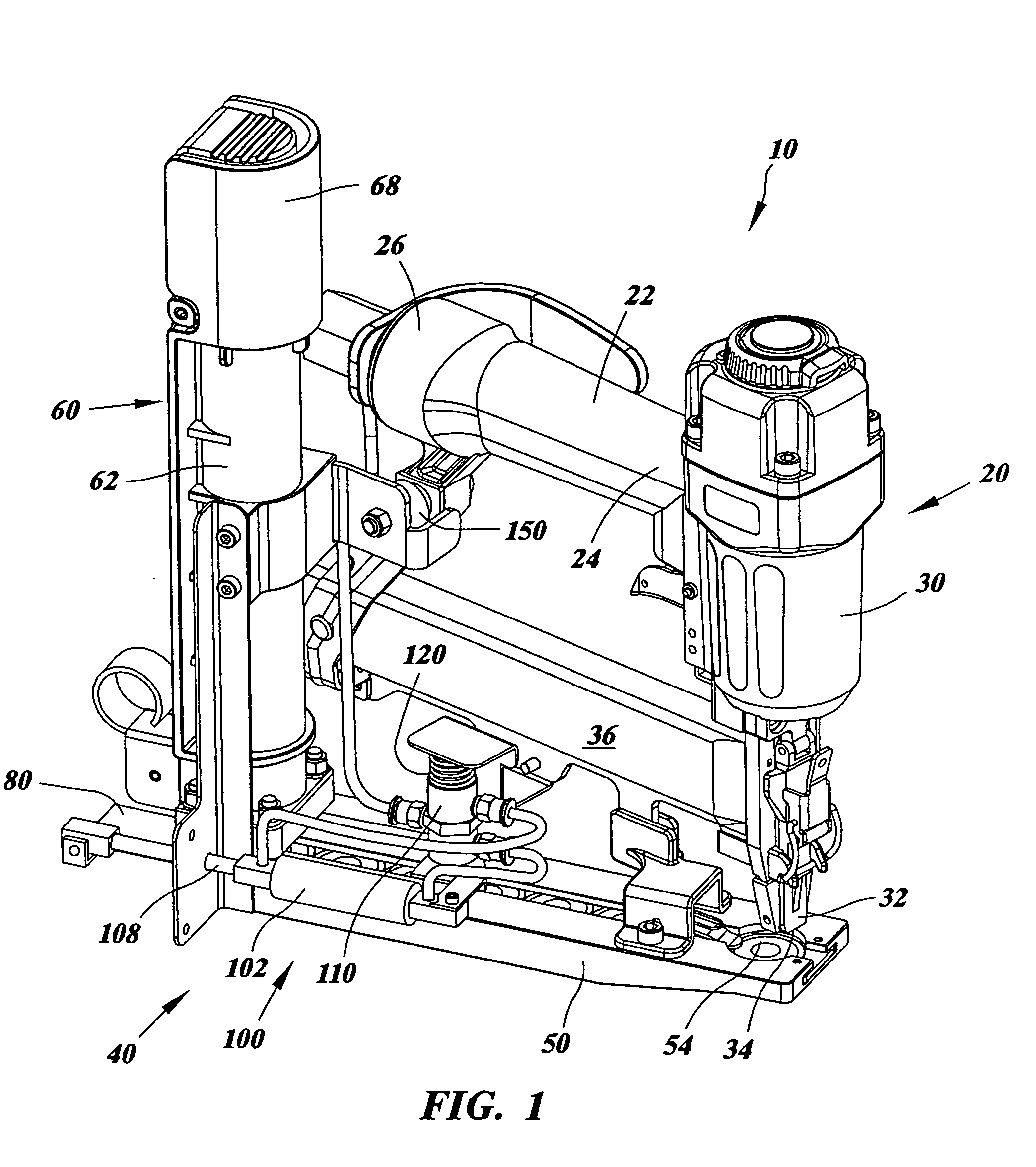
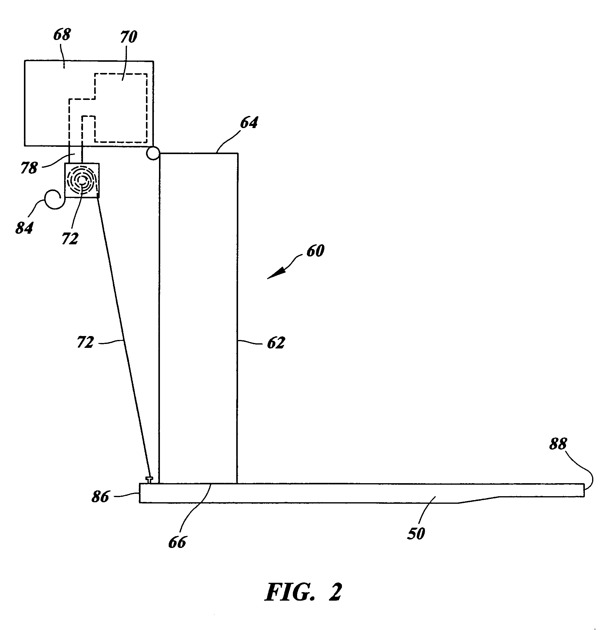
[0052]FIGS. 1–8 illustrate one example of the staple or nail gun assembly 10 of the present invention. The staple or nail gun assembly 10 includes a staple or nail gun 20 and a cap feeding device 40. The staple or nail gun 20 has a handle portion 22 and a head portion 30. The handle portion 22 has front and rear ends 24, 26, the front end 24 being attached to the head portion 30. The cap feeding device 40 includes a base 50, a cap container 60 and a shuttle 80. The base 50 includes a cap feeding chamber 52 and a cap holding chamber 54, and a channel 56 connecting the two chambers 52, 54. The container 60 is used to store staple or nail caps 140 and to feed the caps 140 to the cap feeding chamber 52 of the base 50 one cap at a time. The shuttle 80 is movably disposed in the channel 56 of the base 50 and is adapted to move a cap at the cap feeding chamber 52 towards the cap holding chamber 54 through the channel 56.

[0053]In the preferred embodiment shown in FIG. 1, the staple or nail ...


PUM


Abstract

A staple or nail gun assembly includes a staple or nail gun, a cap feeding device and a cap having a peripheral rim disposed on its underside, a marginal edge on its upper side adjacent a central portion having the shape of a truncated cone. The staple or nail gun and the cap feeding device are generally disposed at opposite ends of the handle of the staple or nail gun. The cap feeding device includes a base, a cap container and a shuttle, and feeds caps sequentially as they are affixed by the gun. The caps are coaxially stacked by means of a coaxial plastic cord or wire with retaining means at the respective ends or in a tubular container with a flanged end. The caps may also be stacked on a rod or held together by melting.

Description

CROSS-REFERENCE TO RELATED APPLICATIONS[0001]This application is a continuation-in-part of pending U.S. Non-Provisional application Ser. No. 10 / 435,737 (filed May 9, 2003), also entitled “Stacked Assembly of Roofing Caps” and fully included herein by reference, and claims priority benefit thereof and of the parent applications of said application Ser. No. 10 / 435,737. application Ser. No. 10 / 435,737, in turn, was a division of pending U.S. Non-Provisional application Ser. No. 09 / 648,335 (filed Aug. 25, 2000), entitled “Staple or Nail Gun Assembly, Cap Gun Feeding Device for Staple or Nail Gun, and Cap Assembly” and fully included herein by reference, and claims priority benefit thereof and of the parent applications of said application Ser. No, 09 / 648,335. application Ser. No. 09 / 648,335, in turn, was a continuation-in-part of U.S. Non-Provisional application Ser. No. 09 / 438,983 (filed Nov., 12, 1999), entitled “Staple or Nail Gun Assembly, Cap Feeding Device for Staple or Nail Gun, ...

Claims


Application Information

Patent Timeline
Patent Type & Authority Patents(United States)
IPC IPC(8): F16B43/00B65D85/00B25C1/00B25C5/16
CPCB25C1/006E04D15/04B25C5/1693E04D2015/045
Inventor LAMB, FREDERICK W.
Owner PNEUTOOLS
Why Eureka
Try Eureka