Eureka AIR delivers breakthrough ideas for toughest innovation challenges, trusted by R&D personnel around the world.

Terminal fitting

a technology of terminal fittings and fittings, applied in the direction of contact member manufacturing, coupling device connection, contact member penetrating/cutting insulation/cable strands, etc., can solve problems such as poor operation feeling, and achieve the effect of stable insertion resistan

Inactive Publication Date: 2006-08-15
SUMITOMO WIRING SYST LTD
View PDF11 Cites 3 Cited by
  • Summary
  • Abstract
  • Description
  • Claims
  • Application Information

AI Technical Summary

Benefits of technology

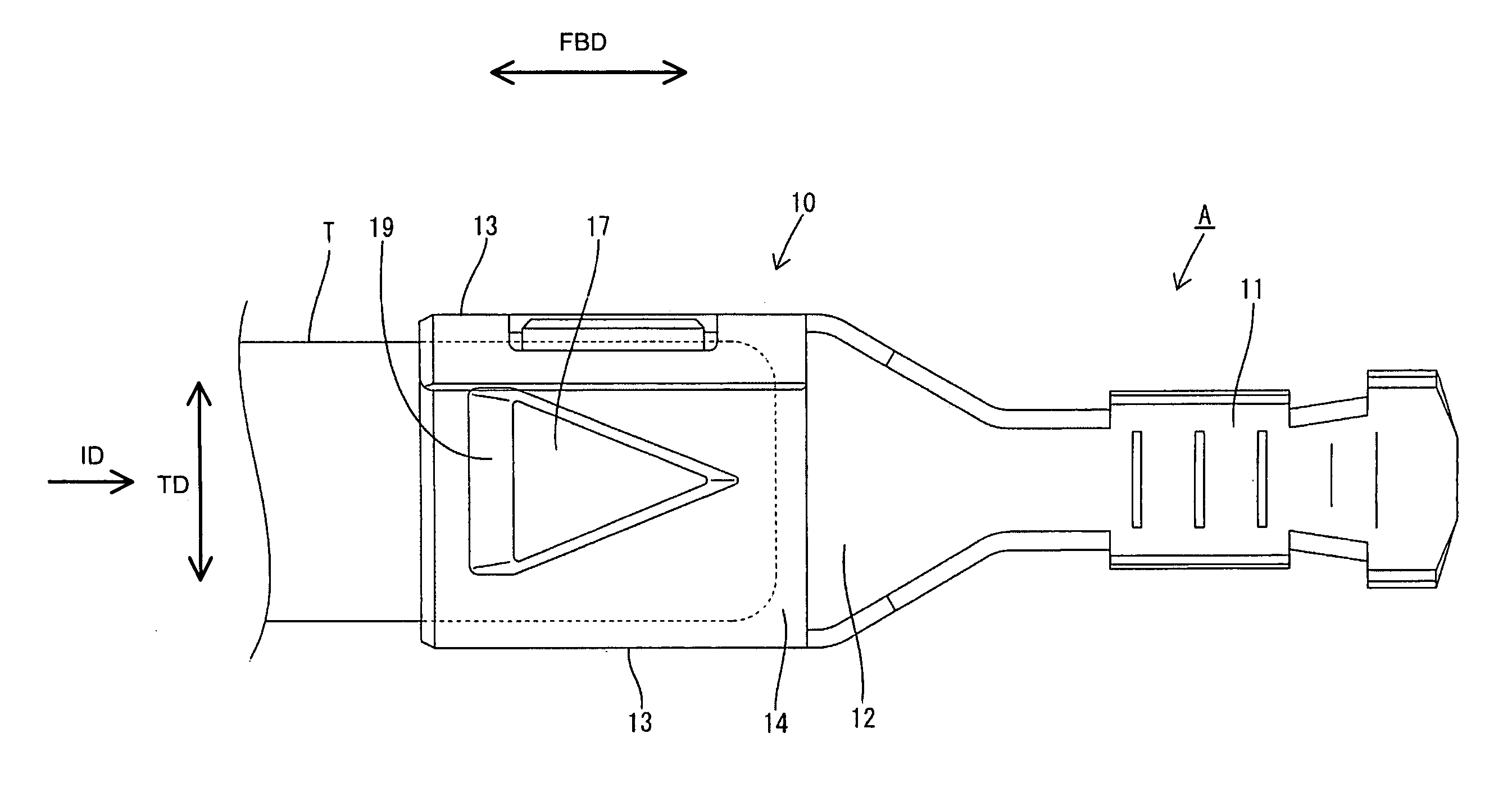
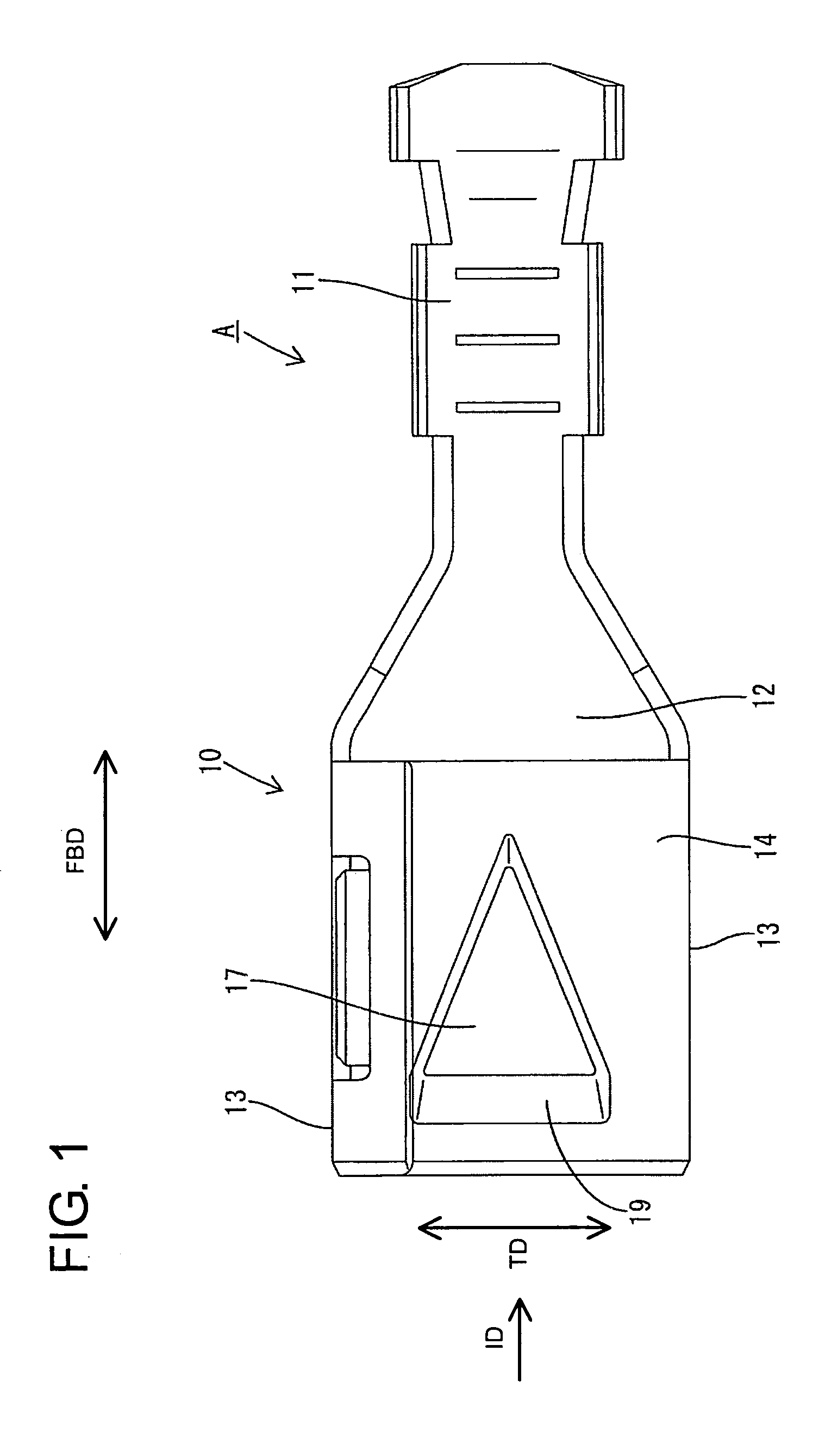
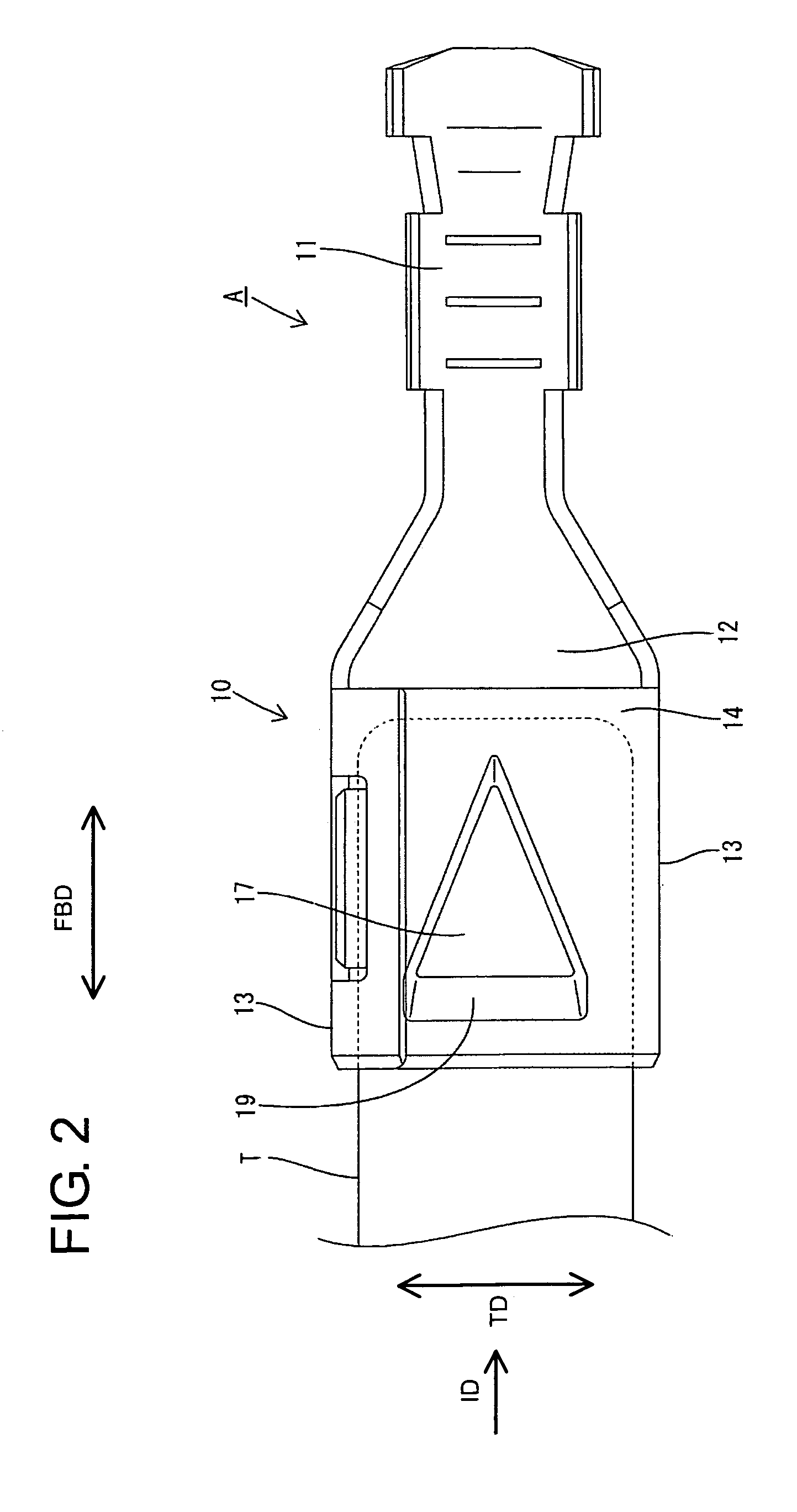
[0008]The contact area between the male tab and the contact surface of the receiving portion necessarily increases during the tab insertion process. However, the rate of increase is smaller for the above-described contact surface, as compared to a substantially rectangular contact surface having a constant width. Experiments demonstrate the value of the insertion resistance for a terminal fitting with the above-described contact surface did not increase to a large extent as the insertion stroke of the male tab increased and a maximum value of the insertion resistance was relatively small. Thus, the terminal fitting of the present invention provides good operation feeling upon manually connecting the male tab with the terminal fitting.
[0011]Since the width of the contact surface decreases at a constant rate along the inserting direction of the male tab, the insertion resistance is stable.

Problems solved by technology

Accordingly, there has been a problem of poor operation feeling upon manually connecting the male tab T with the terminal fitting B.

Method used


Image

  • Terminal fitting
  • Terminal fitting
  • Terminal fitting

Examples


Embodiment Construction

[0024]The letter A in FIGS. 1 TO 5 identifies a female terminal fitting in accordance with the subject invention. The terminal fitting A is long and narrow in forward and backward directions FBD. A substantially rectangular tube 10 is formed at a front side of the terminal fitting A, and a wire connecting portion 11 is formed at a rear side. The wire connecting portion 11 is an open barrel that can be crimped, bent or folded into connection with a wire (not shown). The rectangular tube 10 has a bottom plate 12 that is continuous and narrow along forward and backward directions FBD over substantially the entire length of the terminal fitting A. Side plates 13 stand up from the opposite lateral edges of the bottom plate 12, and a substantially horizontal upper plate 14 extends from the upper edge of one side plate 13 towards the opposite side plate 13. The upper plate 14 is substantially parallel with the bottom plate 12. The terms upper and lower are used herein to provide a convenie...


PUM


Abstract

A terminal fitting (A) has a receiving portion (17) with a contact surface (18) for contacting a male tab (T). The contact surface (18) is widest at the front end and substantially narrowed toward the back. A rate at which a contact area of the male tab (T) and the contact surface (18) increases in the insertion process of the male tab (T) is smaller as compared to a substantially rectangular contact surface having a constant width. The terminal fitting (A) provides good operation feeling upon manually connecting the male tab (T) with the terminal fitting (A).

Description

BACKGROUND OF THE INVENTION[0001]1. Field of the Invention[0002]The invention relates to a terminal fitting.[0003]2. Description of the Related Art[0004]Japanese Unexamined Utility Model Publication No. S63-35274 discloses a female terminal fitting with opposite front and rear ends. A rectangular tube is formed at the front end and is configured to receive a male tab inserted from the front. A resilient contact is arranged inside the rectangular tube, and a receiving portion is embossed on a wall of the rectangular tube to project toward the resilient contact. The receiving portion is parallel with an inserting direction of the male tab. The male tab inserted into the rectangular tube is squeezed resiliently between the receiving portion and the resilient contact, and is held in surface contact with the receiving portion.[0005]The above-described prior art terminal fitting is illustrated in FIG. 6(A) and is identified by the letter B. The terminal fitting B has a substantially recta...

Claims


Application Information

Patent Timeline
Patent Type & Authority Patents(United States)
IPC IPC(8): H01R13/187H01R13/11H01R4/48H01R13/115H01R13/193
CPCH01R13/193H01R13/113H01R4/4872H01R43/16
Inventor MORIKAWA, TAKASHI
Owner SUMITOMO WIRING SYST LTD
Why Eureka
Eureka Blog
Learn More