Multi-spot laser surgical apparatus and method

a laser and multi-spot technology, applied in the field of array of light beams, can solve the problems of less power, less suited to traditional laser systems, and more expensive laser types,

Inactive Publication Date: 2006-08-15
RELIANT TECH INC
View PDF128 Cites 65 Cited by
  • Summary
  • Abstract
  • Description
  • Claims
  • Application Information

AI Technical Summary

Benefits of technology

[0011]In one embodiment, multiple laser diodes are coupled into optical fibers. The terminating ends of the optical fibers are aligned into a 1×N array and imaged onto the treatment area to generate the spots. The total length of the array is approximately 1 cm. The array is dithered to form an irregular pattern of spots (e.g., see FIG. 3). The travel for the dithering is approximately equal to the spacing between light beams in the array. The dithering is accomplished by components in a hand piece; the hand piece is swept along the main scan direction. A main scan sensor tracks the velocity of the sweeping and a controller adjusts the dithering accordingly. The controller also controls the exposure of the light beams on the treatment area so that the spots are not over- or underexposed.

Problems solved by technology

Traditional laser systems are not well suited for these applications because the laser beams generated by traditional systems typically are too large and too energetic.
Traditional systems also are typically based on more expensive types of lasers and do not take advantage of lower power, cheaper semiconductor lasers.
In addition, the single laser beam generated by traditional systems would have to be individually positioned to generate each of the spots in the overall pattern and, since there typically are a large number of spots in the pattern, the required scan time becomes unacceptably long.

Method used


Image

  • Multi-spot laser surgical apparatus and method
  • Multi-spot laser surgical apparatus and method
  • Multi-spot laser surgical apparatus and method

Examples


Embodiment Construction

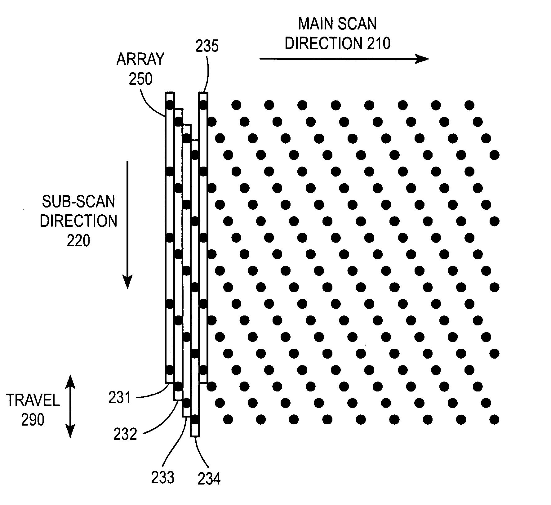
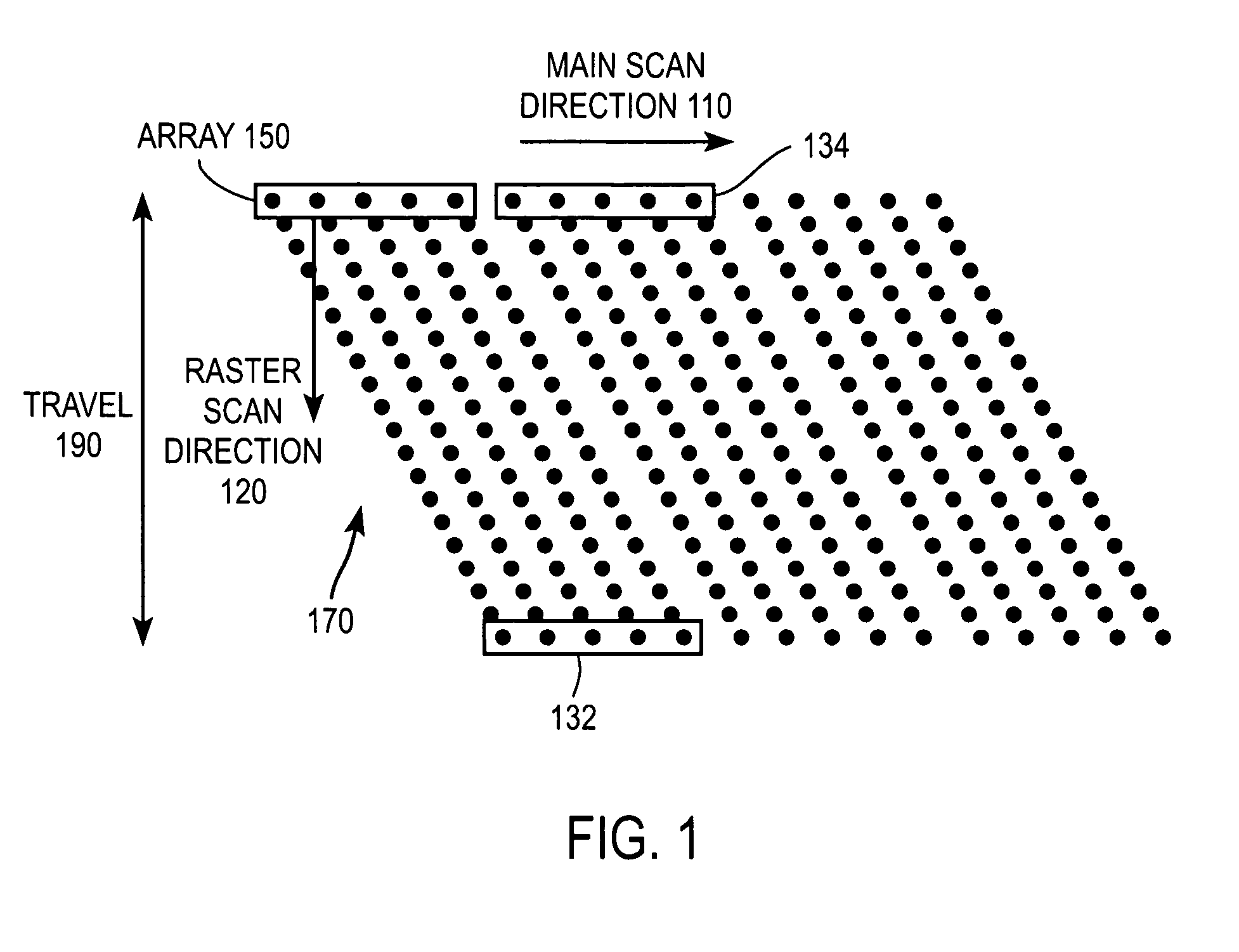
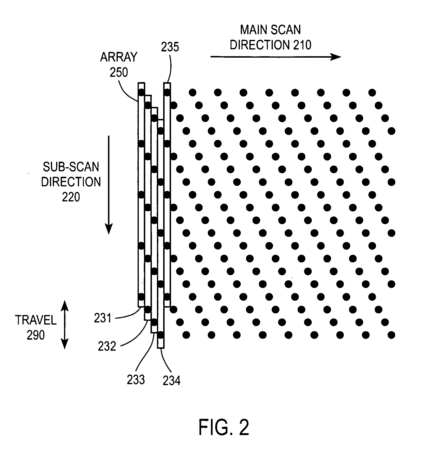
[0020]FIG. 1 shows a raster pattern for generating a pattern of spots. The row 150 of laser beams is aligned to the main scan direction 110 (i.e., the direction in which the physician sweeps the hand piece). While the array 150 is swept along the main scan direction 110, it is also raster scanned in the transverse direction 120. The laser beams are pulsed during this movement to produce the pattern of spots shown in FIG. 1. At the end 132 of each raster scan, the array is “reset” to the start position 134 of the next raster scan.

[0021]While this approach has many advantages compared to individually positioning a single laser beam to generate each of the spots in the pattern, one disadvantage of this approach is the travel 190 of the array 150 in the raster scan direction 120 can be long in certain applications. If the raster scan is accomplished by mechanically translating the light source, then the long travel increases the mechanical wear and tear and reduces the life of the syste...


PUM


Abstract

An array of light beams is swept along a main scan direction and dithered in a sub-scan direction to generate a treatment pattern of spots. The array is elongated along the sub-scan direction and the dithering has a travel that is significantly less than the length of the array in the sub-scan direction.

Description

BACKGROUND OF THE INVENTION[0001]1. Field of the Invention[0002]This invention relates generally to an array of light beams used to generate a pattern of spots, for example as can be employed in laser surgery and laser dermatology.[0003]2. Description of the Related Art[0004]In laser surgical applications, for example in laser dermatology, an optical system generates a light beam(s) of a desired size and energy and this light beam is used to treat a selected region of the patient's body (i.e., the treatment area). For example, in many dermatology applications, a hand piece is used to guide the laser beam to the treatment area. The hand piece is typically attached to one end of an articulated arm, which transmits the laser beam to the hand piece and also supports a wide range of motion for the hand piece.[0005]A physician typically treats the treatment area by sweeping the laser hand piece back and forth over the treatment area. In many cases, the physician is guided by an aiming lin...

Claims


Application Information

Patent Timeline
Patent Type & Authority Patents(United States)
IPC IPC(8): A61B18/18A61B18/20A61N5/01A61N5/067
CPCA61B18/203A61B2018/00452A61B2018/2085A61B2018/208A61B2018/2065A61B2018/20351A61B2018/205545
Inventor SINK, ROBERT K
Owner RELIANT TECH INC
Why Eureka
Try Eureka