
Device for offsetting prosthetic components

a technology for prosthetic components and devices, applied in the direction of rod connections, prosthesis, couplings, etc., can solve the problems of affecting person's gait, compromising person's ability to comfortably walk, and affecting the use of these devices

Inactive Publication Date: 2006-08-15
AMERICAN PROSTHETIC COMPONENTS
View PDF8 Cites 41 Cited by
  • Summary
  • Abstract
  • Description
  • Claims
  • Application Information

AI Technical Summary

Benefits of technology

The device ensures proper alignment and comfort by allowing precise adjustments of prosthetic components, reducing stress concentrations and extending the lifespan of prosthetic limbs by accommodating imperfect length determinations.

Problems solved by technology

This device, as well as other alignment devices, may work well for their intended purpose, but their use carries with them some undesirable consequences.
The person's ability to comfortably walk can be compromised when the prosthetic components are in an offset alignment.
One problem that occurs when the prosthetic components are offset is that the person's gait is affected.
Another problem associated with offset prosthetic components is that the person's weight may not be centered over the lowermost prosthetic components.
This can affect not only the person's comfort, but also can cause unintended stress concentrations to develop within the prosthetic limb.
This may lead to damage to or failure of the prosthetic limb.
Hence, the connecting part provides for only limited adjustability, and provides for no adjustability other than due to the interfaces between the connecting part and the other prosthetic components.
If the screw head fails, the entire component could fail.
A further undesirable aspect of the Hossmer Dorrance Corporation components is that an adapter is needed to allow for adjustments to be made in both the lateral-medial directions and the anterior-posterior directions.
A still further undesirable aspect of the Hossmer Dorrance Corporation components is that those components are not shown to be extendable or adjustable in a direction generally parallel to the longitudinal axis of the prosthetic components that they connect to.
Due to this lack of adjustability, the Hossmer Dorrance Corporation components are incapable of being used to selectably adjust the length of a prosthetic limb.
This may lead to unsatisfactory results unless the other components used in combination with the Hossmer Dorrance Corporation components are capable of making longitudinal adjustments, or unless the other components are exactly properly sized, so that the prosthetic limb will have a correct length.

Method used


Image

  • Device for offsetting prosthetic components
  • Device for offsetting prosthetic components
  • Device for offsetting prosthetic components

Examples


Embodiment Construction

[0040]While the invention will be described in connection with a preferred embodiment, it will be understood that it is not intended to limit the invention to that embodiment. On the contrary, it is intended to cover all alternatives, modifications and equivalents as may be included within the spirit and scope of the invention as defined by the appended claims.

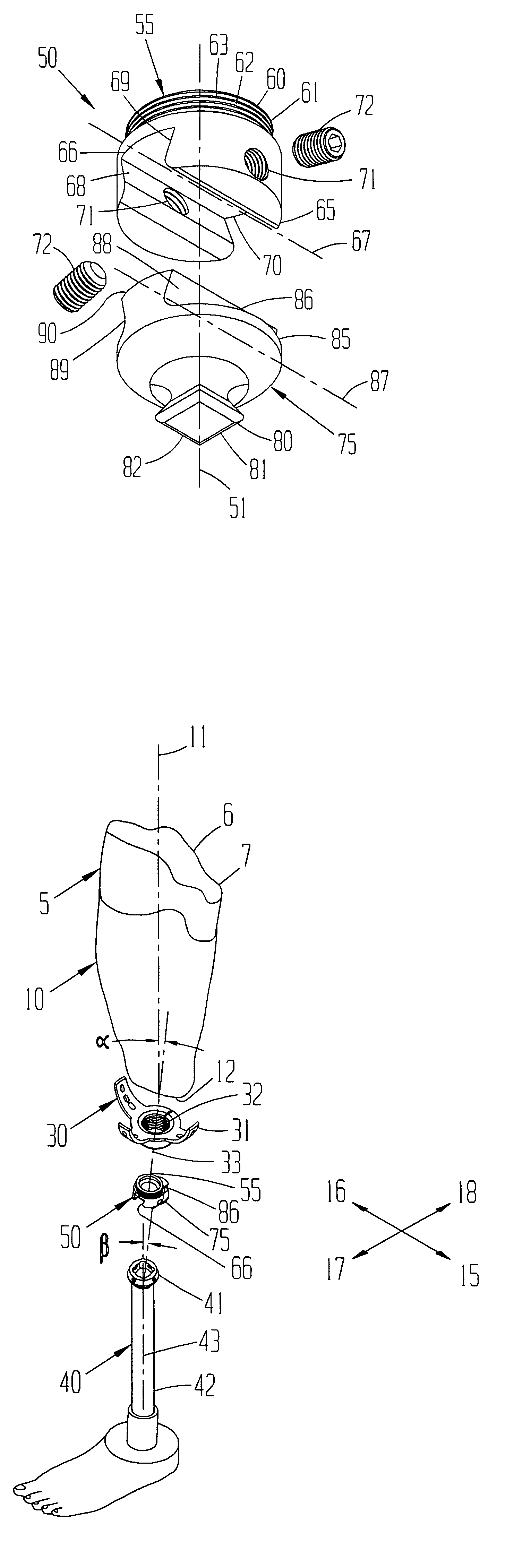
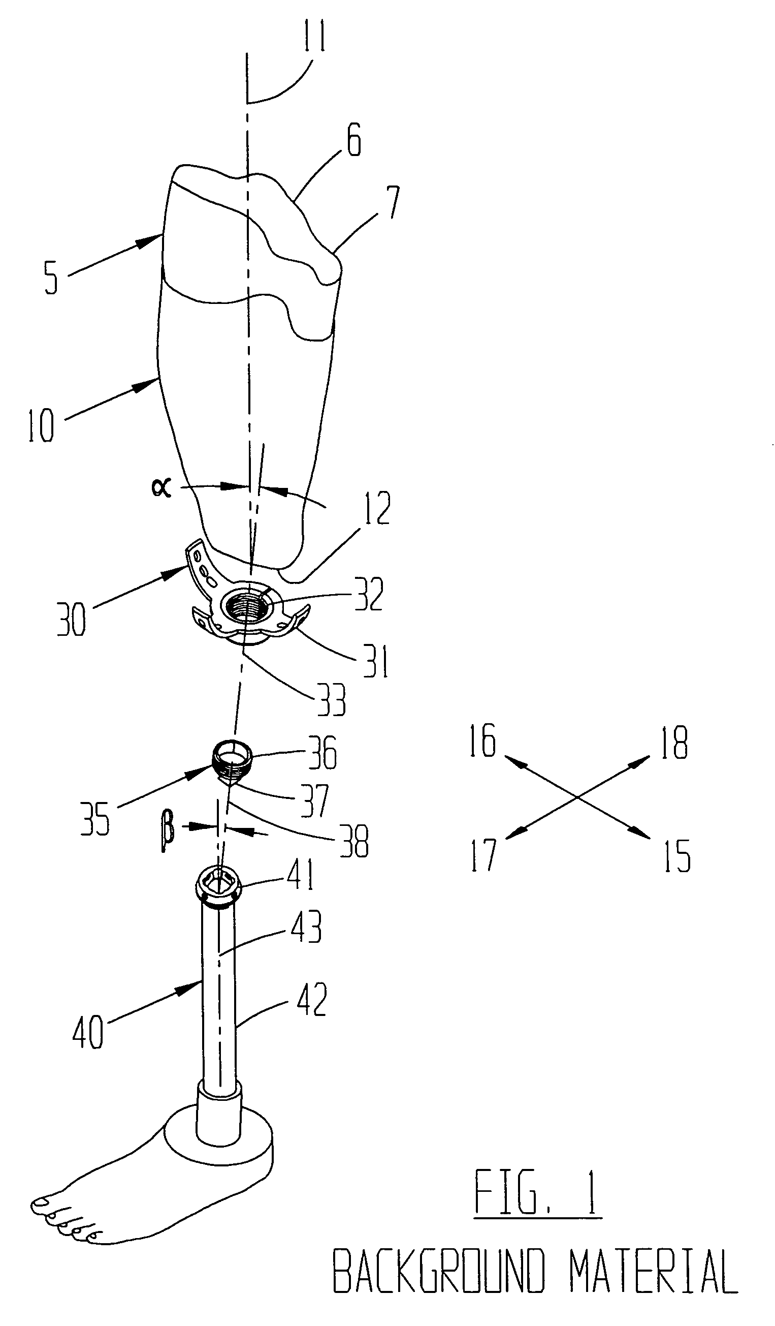
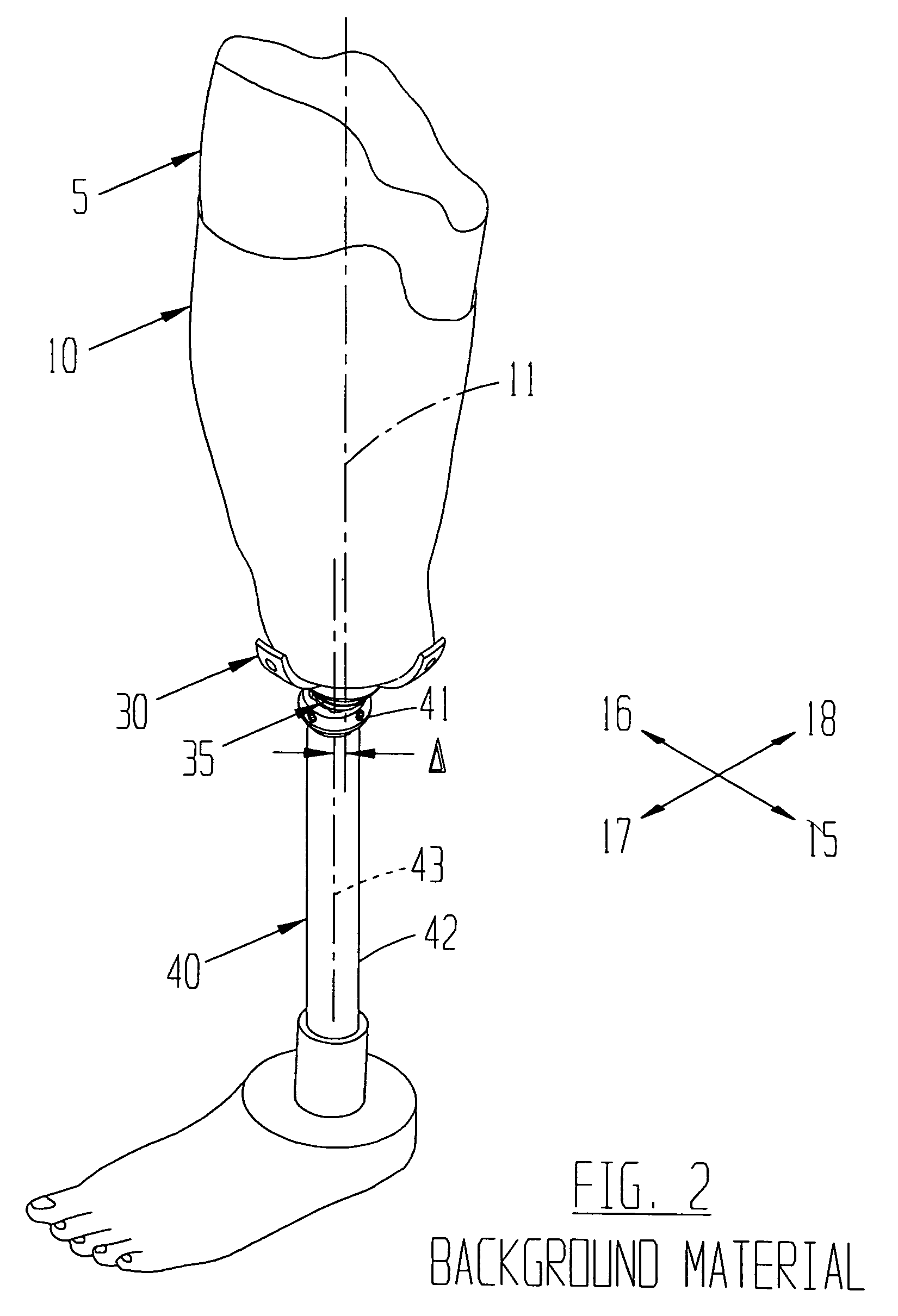
[0041]The present invention is intended for use with a prosthetic limb. A person 5 having a limb 6 terminating in a stump 7 may have prosthetic limb. A conventional set up is shown in FIGS. 1 and 2, where the prosthetic limb has a socket 10 with a socket central axis 11 and an end 12. The socket 10 can be angularly offset from the remainder of the prosthetic component by angle alpha. A three prong adapter 30 having prongs 31, an internally threaded end 32 and a central axis 33 can be connected to the socket 10.

[0042]Another component, such as a pyramidal adapter 35 can be connected to the three prong adapter 30. The pyramidal ...


PUM


Abstract

An offset alignment device with a longitudinal axis is provided that can offset two prosthetic components a selected distance along an alignment axis that is selectably oriented in a plane that is generally perpendicular to the longitudinal axis, and can also adjust the distance between the two prosthetic components in a direction generally parallel to the longitudinal axis. The present invention comprises first and second members. The first member has a channel and the second member has a bar for being adjustably connected to the channel along the alignment axis. A set screw can be through a hole in the wall of the channel in a direction generally perpendicular to the alignment axis to contact the bar and hold it stationary within the channel. One or both of the first and second members can be rotatably connected to one or both of the first and second prosthetic components, respectively.

Description

BACKGROUND OF THE INVENTION[0001]1. Field of the Invention[0002]The present invention relates to a device for offsetting two prosthetic components that are connected to opposite ends of the present invention wherein the first prosthetic component is offsetable in both the anterior-posterior and the lateral-medial directions from the second prosthetic component a selected distance along a single offsetting axis.[0003]2. Description of the Related Art[0004]Sometimes, due to accidents, health problems, birth defects, etc., people 5 need to have a limb 6 amputated. The amputated limb 6 terminates in a stump 7. In general, a socket 10 can be formed for any particular stump 7. Those sockets 10 are well known in the art, and each socket 10 has a central axis 11.[0005]Fortunately for people requiring a prosthetic limb, much advancement has been made in the field of prosthetic limbs. Patients now have many choices, including endoskeletal and exoskeletal prosthetic limbs. The present inventio...

Claims


Application Information

Patent Timeline
Patent Type & Authority Patents(United States)
IPC IPC(8): A61F2/62A61FA61F2/00A61F2/50A61F2/60A61F2/74A61F2/76A61F2/80
CPCA61F2/76A61F2/60Y10T403/7041A61F2/80A61F2002/30359A61F2002/30387A61F2002/30405A61F2002/30433A61F2002/5018A61F2002/5023A61F2220/0025A61F2220/0033A61F2220/0041Y10T403/32598Y10T403/7094F16B2200/30
Inventor CURTIS, MICHAEL J.
Owner AMERICAN PROSTHETIC COMPONENTS
Learn More