Disconnect switch

a technology of disconnect switch and short circuit, which is applied in the direction of air break switch details, contact, air break switch, etc., can solve the problems of relatively high switch cost, low short circuit rating of spring switch, and inability to respond well to 80 ka short circuit in three-phase non-segregated applications. , to achieve the effect of improving the short circuit rating of the switch

Active Publication Date: 2006-08-15
GENERAL ELECTRIC CANADA MISSISSAUGA
View PDF5 Cites 15 Cited by
  • Summary
  • Abstract
  • Description
  • Claims
  • Application Information

AI Technical Summary

Benefits of technology

[0006]In one embodiment, each of the fingers comprises an inside surface comprising first and second spaced apart raised portions. The first raised portion comprises a first flat surface area portion adapted to contact the second end portion of the switch blade and the second raised portion comprises a second flat surface area portion adapted to contact the second electrical terminal when the switch blade is in the closed position. These flat portions on each of the fingers increase the contact surface area between the fingers and the switch blade, and between the fingers and the second terminal connector to thereby improve the short circuit rating of the switch.
[0009]By utilizing a removable finger end portion, the assembly of the fingers onto the finger end portion is possible prior to assembly of the finger end portion between the blade members resulting in easier assembly. Also, the replacement of the entire finger end portion can be made in the event one or more of the fingers becomes welded to the head portion of the finger end portion without having to replace the blade members.

Problems solved by technology

While this spring switch configuration provides a reliable switch for making and breaking the connection at the second electrical terminal, the spring switch does not respond well to 80 kA short circuits in the three phase non-segregated application.
While the bolted switch is able to withstand the 80 kA short circuit condition, this switch is relatively expensive to manufacture and tends not to be as reliable over time in making and breaking the connection with the second electrical terminal.

Method used


Image

  • Disconnect switch
  • Disconnect switch
  • Disconnect switch

Examples


Embodiment Construction

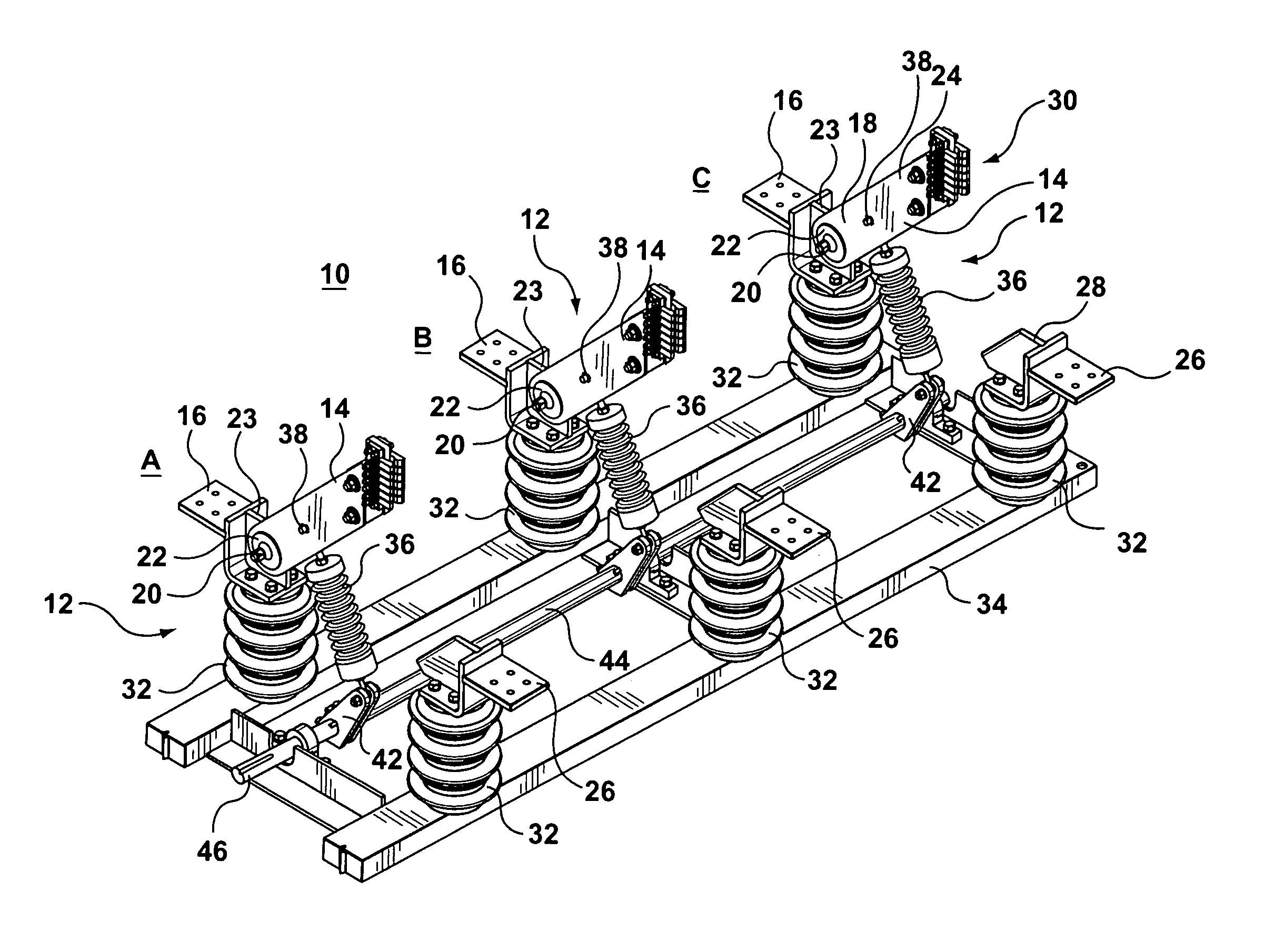
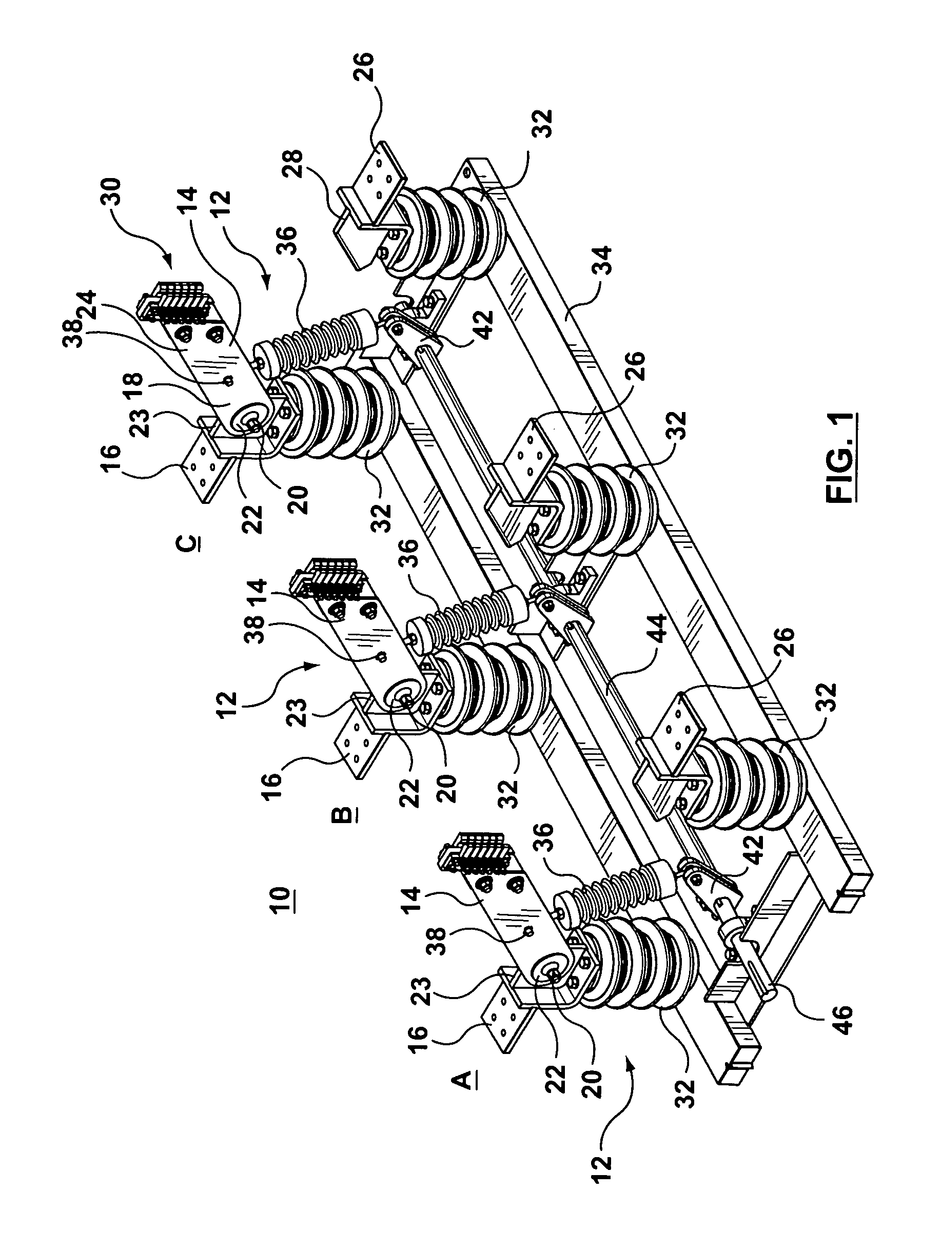
[0017]Referring to FIG. 1 there is shown a three phase non-segregated disconnect switch 10. The three phase non-segregated switch 10 comprises three switches 12 for disconnecting power across phases A, B, and C. Typically, these phases are for alternating electrical current that is 120 degrees out of phase with each other.

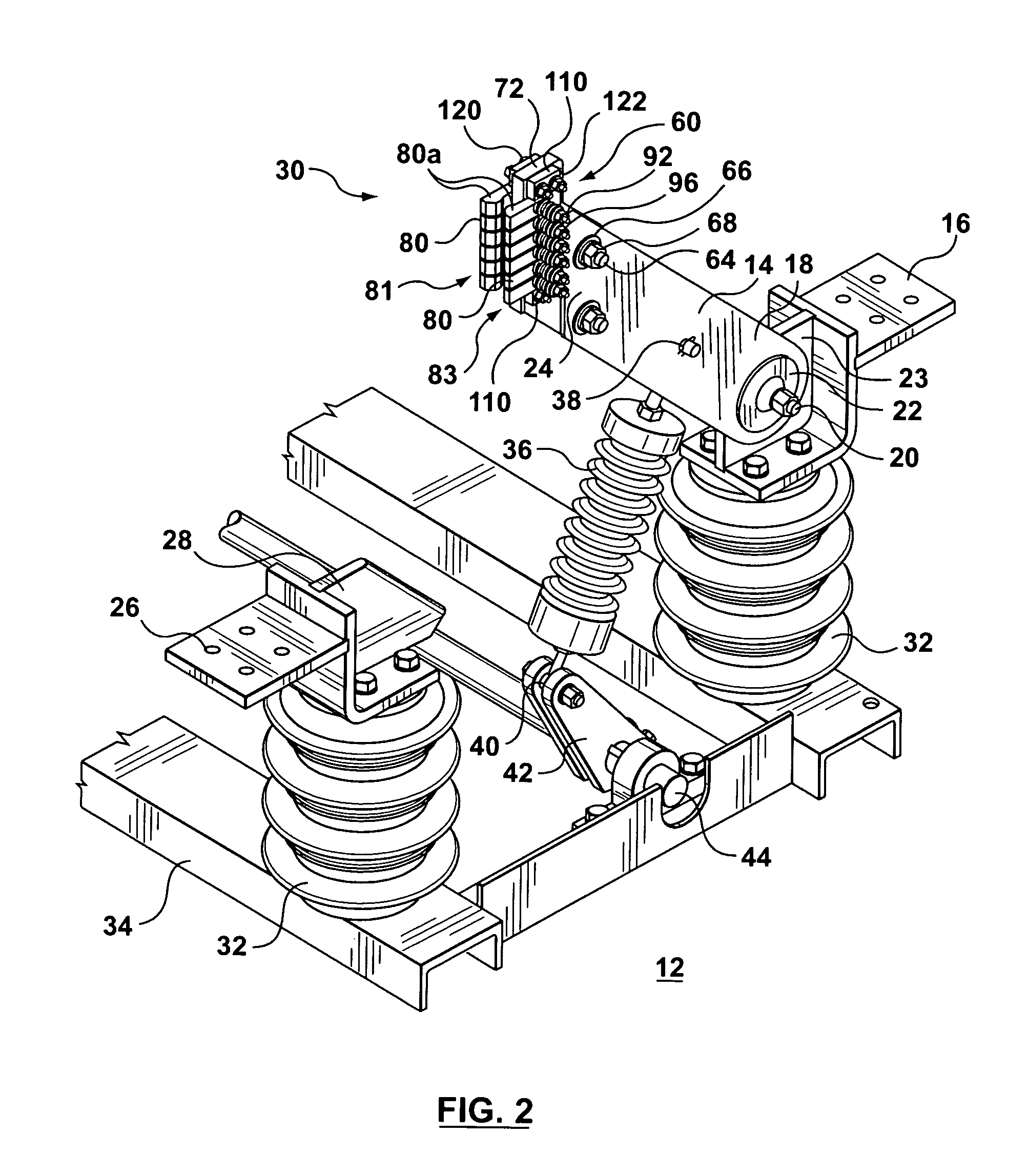
[0018]Each of the switches 12 comprises an elongate conductive switch blade 14 shown in FIGS. 1 and 2 in the open position. Each of the switches 12 further comprises a first electrical terminal 16 to which a first end portion 18 of the switch blade 14 is pivotally connected by a bolt and nut fastener 20 and a pair of Belleville washers 22 pressing on opposing sides of the first end portion 18 of the blade 14. The first electrical terminal 16 has a blade like connector portion 23 to which the blade 14 is pivotally connected by bolt and nut fastener 20.

[0019]The switch blade 14 has a second end portion 24 which is adapted to bridge the first electrical terminal 16 wi...


PUM


Abstract

A switch has a first electrical terminal, a second electrical terminal spaced from the first electrical terminal and an elongate conductive switch blade for bridging the terminals. The switch blade has a first end portion pivotally connected with the first electrical terminal for movement of the switch blade between open and closed positions. The switch blade has a second end portion positioned adjacent the second electrical terminal when in the closed position. A plurality of elongate fingers are secured by spring loading to the second end portion of the switch blade. The fingers are arranged adjacent to each other along opposing sides of the second end portion to form an open jaw structure that extends from the second end portion of the switch blade and makes wiping electrical contact with the second electrical terminal as the switch blade is moved into the closed position.

Description

FIELD OF THE INVENTION[0001]The present invention relates to a disconnect switch with blades and fingers and in particular a switch suitable for use in three phase non-segregated high current applications.BACKGROUND OF THE INVENTION[0002]Three phase non-segregated disconnect switches find application in generator compartments for supplying electricity to a power grid. These switches must be capable of withstanding short circuit tests in the order of 80 kA.[0003]One type of disconnect switch used in the three phase non-segregated application comprises a pair of spaced apart elongated blade members which span the distance between first and second electrical terminals of the switch. Typically these spaced apart blades include a spacer between the blades. One end of the blades is pivotally attached to one of the terminals and the other end of the blades has inside edges of the blades making wiping contact with the second electrical terminal. In this switch, as many as three bolts pass t...

Claims


Application Information

Patent Timeline
Patent Type & Authority Patents(United States)
IPC IPC(8): H01H31/02
CPCH01H1/42H01H31/30H01H2001/425H01H31/026
Inventor ARCAND, SEBASTIENCOTE, SEBASTIEN
Owner GENERAL ELECTRIC CANADA MISSISSAUGA
Why Eureka
Try Eureka