Electric arc welding system

a technology of electric arc welding and welding system, which is applied in welding apparatus, metal working apparatus, manufacturing tools, etc., can solve the problems of limiting the penetration of a given reinforcement level, reducing the penetration rate of molten metal in the weld pool, and disrupting the welding process. , to achieve the effect of high penetration, high deposition, and increased heat inpu

Active Publication Date: 2006-08-15
LINCOLN GLOBAL INC
View PDF11 Cites 15 Cited by
  • Summary
  • Abstract
  • Description
  • Claims
  • Application Information

AI Technical Summary

Problems solved by technology

If the adjacent AC pulses have a long time, exceeding 20 ms, with a concurrent polarity relationship, the collapsing or repelling action of the molten metal in the weld pool is disruptive to the welding process.
The resulting weld bead that subsequently solidifies is not uniform.
This limits the penetration for a given reinforcement level.

Method used


Image

  • Electric arc welding system
  • Electric arc welding system
  • Electric arc welding system

Examples


Embodiment Construction

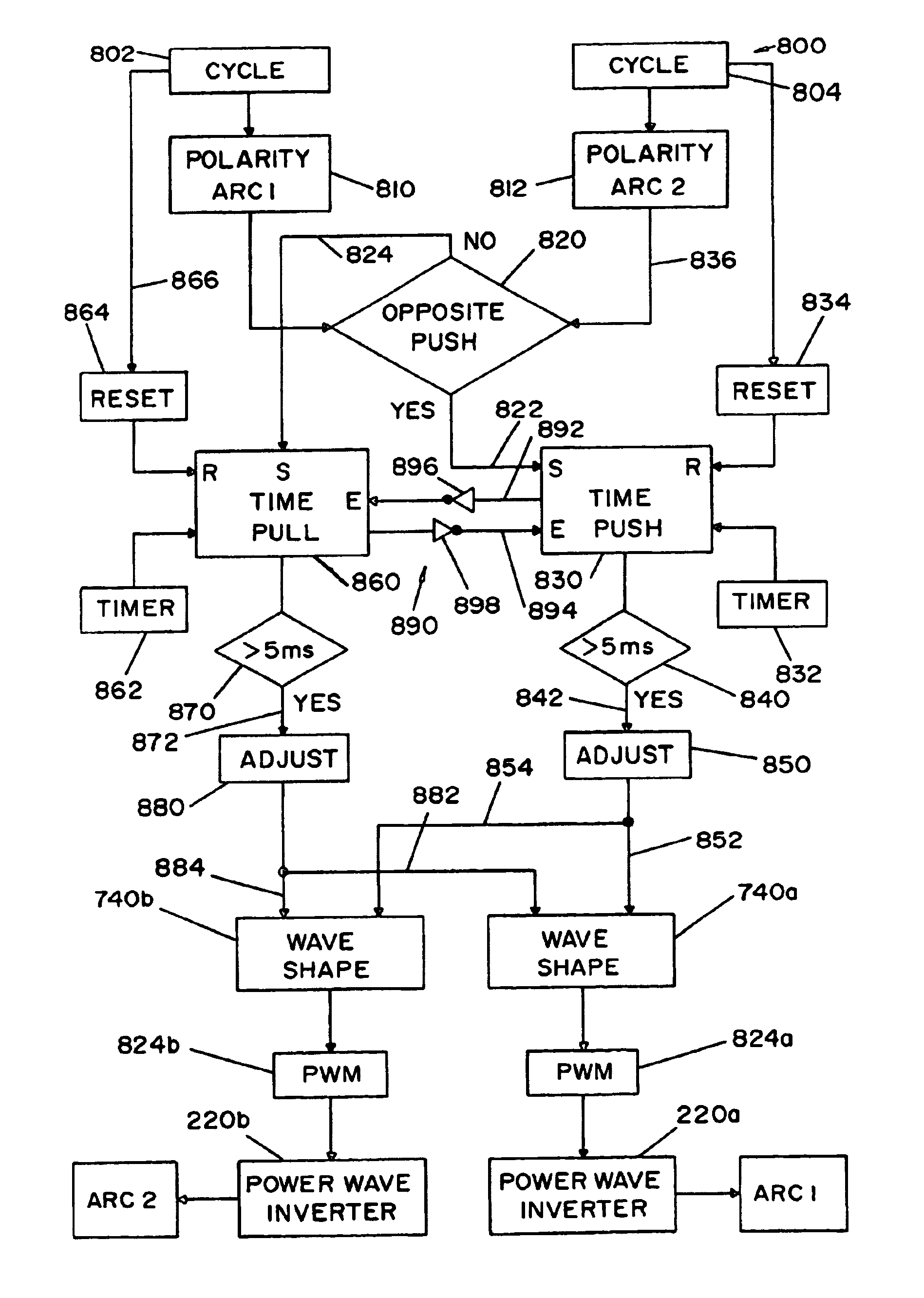
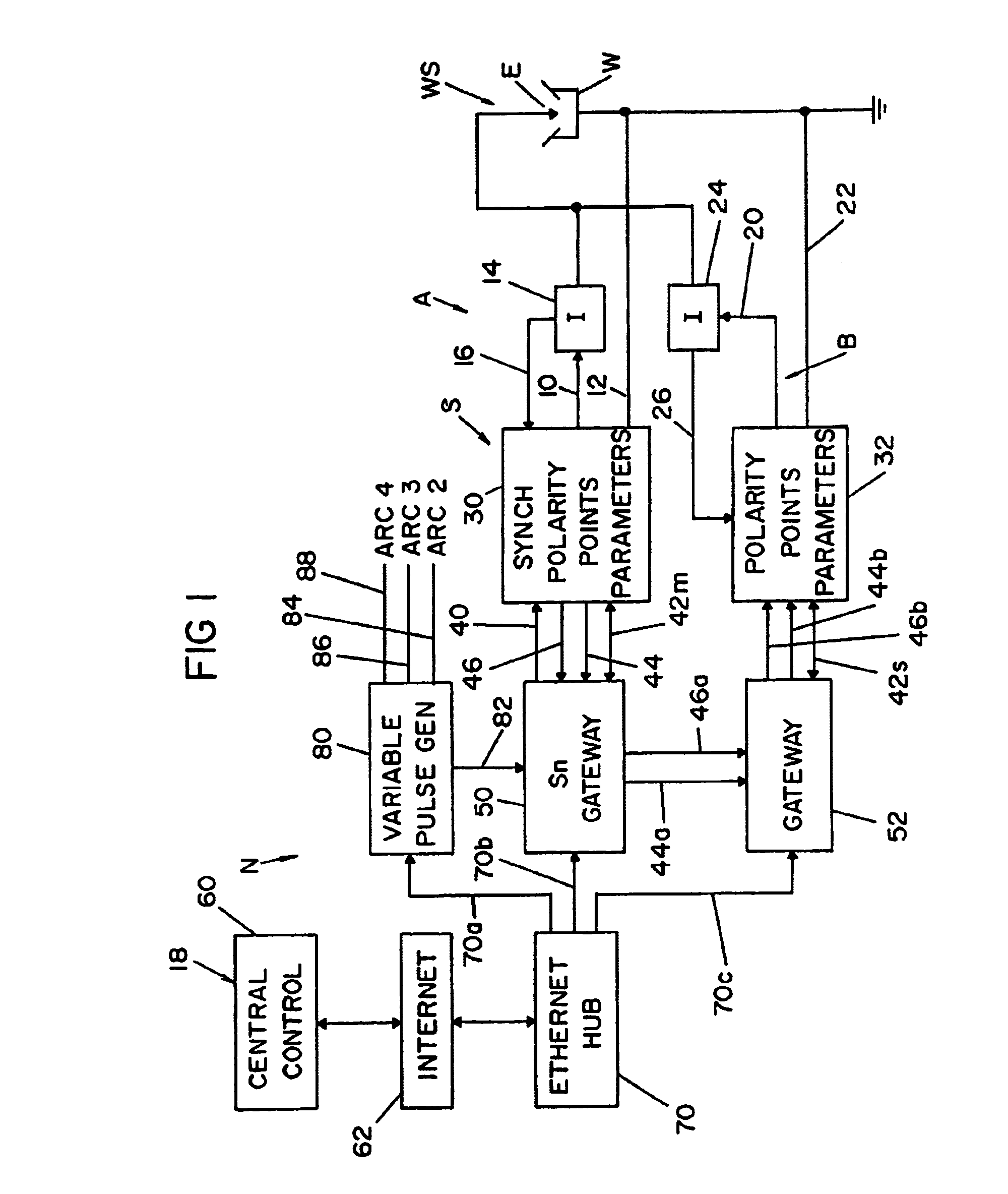
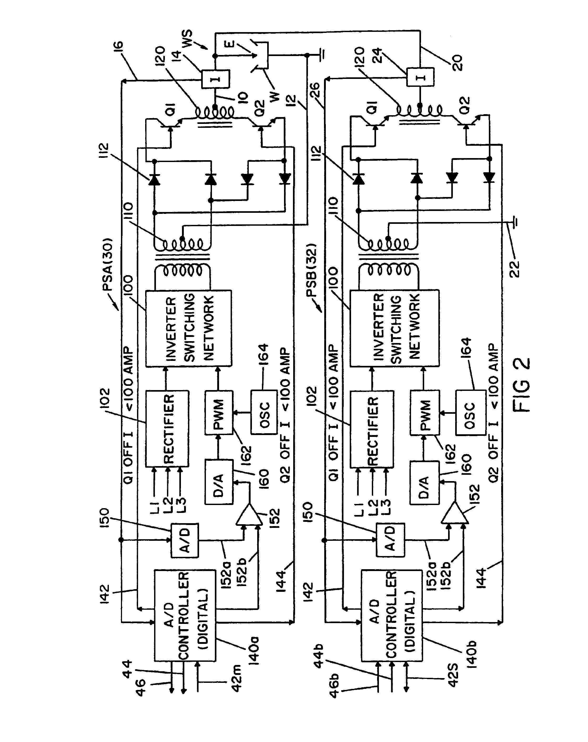
[0038]Referring now to the drawings wherein the showings are for the purpose of illustrating background technology in FIGS. 1–16 and the preferred embodiment of the invention in FIGS. 17–19. This is not for the purpose of limiting the invention. The preferred system for implementing the invention is shown in detail in FIGS. 1, 2 AND 16. In FIG. 1 there is a single electric arc welding system S in the form of a single cell to create an alternating current as an arc at weld station WS. This system or cell includes a first master welder A with output leads 10, 12 in series with electrode E and workpiece W in the form of a pipe seam joint or other welding operation. Hall effect current transducer 14 provides a voltage in line 16 proportional to the current of welder A. Less time critical data, such as welding parameters, are generated at a remote central control 18. In a like manner, a slave following welder B includes leads 20, 22 connected in parallel with leads 10, 12 to direct an ad...


PUM

PropertyMeasurementUnit
frequencyaaaaaaaaaa
push timeaaaaaaaaaa
pull timeaaaaaaaaaa

Abstract

An electric arc welding system and method for creating a first AC welding arc with a first current waveform between a first electrode and a workpiece by a first power supply and a second AC welding arc with a second current waveform between a second electrode and a workpiece by a second power supply as the first and second electrodes are moved in unison along a welding path where the first and second power supply each comprising an high speed switching inverter creating its waveform by a number of current pulses occurring at a frequency of at least 18 kHz with the magnitude of each current pulse controlled by a wave shaper and the polarity of the waveforms controlled by a signal. The first and second AC waveforms each have a positive portion and a negative portion and a cycle period of about 10–20 ms and timing circuits for determining the push and pull times between the arcs and a waveform adjusting circuit to limit the push and pull times to less than about 5.0 ms.

Description

[0001]The present invention relates to the art of electric arc welding and more particularly to an electric arc welding system to operate tandem electrodes.INCORPORATION BY REFERENCE[0002]The present invention is directed to an electric arc welding system utilizing high capacity alternating circuit power supplies for driving two or more tandem electrodes of the type used in seam welding of large metal blanks. Although the invention can be used with any standard AC power supply with switches for changing the output polarity, it is preferred that the power supplies use the switching concept disclosed in Stava U.S. Pat. No. 6,111,216 wherein the power supply is an inverter having two large output polarity switches with the arc current being reduced before the switches reverse the polarity. Consequently, the term “switching point” is a complex procedure whereby the power supply is first turned off awaiting a current less than a preselected value, such as 100 amperes. Upon reaching the 1...

Claims


Application Information

Patent Timeline
Patent Type & Authority Patents(United States)
IPC IPC(8): B23K9/09B23K9/073B23K9/08B23K9/095B23K9/10B23K9/173B23K9/18
CPCB23K9/091B23K9/0953B23K9/188B23K9/1735B23K9/1062B23K9/092Y10S29/013
Inventor HOUSTON, WILLIAM S.MYERS, RUSSELL K.
Owner LINCOLN GLOBAL INC
Why Eureka
Try Eureka