Light generator and exposure apparatus

a light generator and exposure apparatus technology, applied in the field of light generators, can solve the problems of reducing the reflectance of an optical element, contaminating the optical element, and configuration cannot supply the energy necessary to generate plasma to the target material, and achieve the effect of stably generating euv ligh

Inactive Publication Date: 2006-08-15
CANON KK
View PDF20 Cites 26 Cited by
  • Summary
  • Abstract
  • Description
  • Claims
  • Application Information

AI Technical Summary

Benefits of technology

[0007]Accordingly, it is an illustrative object of the present invention to provide a light generator and exposure apparatus that satisfactorily eliminates the debris and stably generates the EUV light.

Problems solved by technology

The laser plasma as one mode of the EUV light source irradiates the high-strength pulse laser light onto the target material and generates not only the EUV light from the target material but also flying particles called debris, which are made of gasified, liquidized and ionized target materials, and cause contaminations, damages and lowered reflectance of an optical element.
This configuration cannot supply the energy necessary to generate the plasma to the target material and stably generate the EUV light.

Method used


Image

  • Light generator and exposure apparatus
  • Light generator and exposure apparatus
  • Light generator and exposure apparatus

Examples


Embodiment Construction

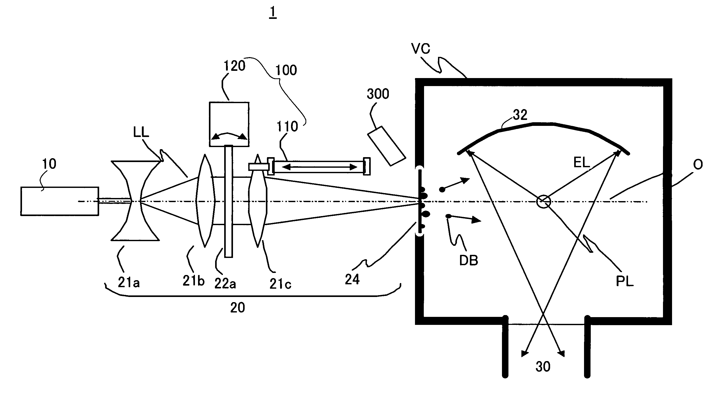
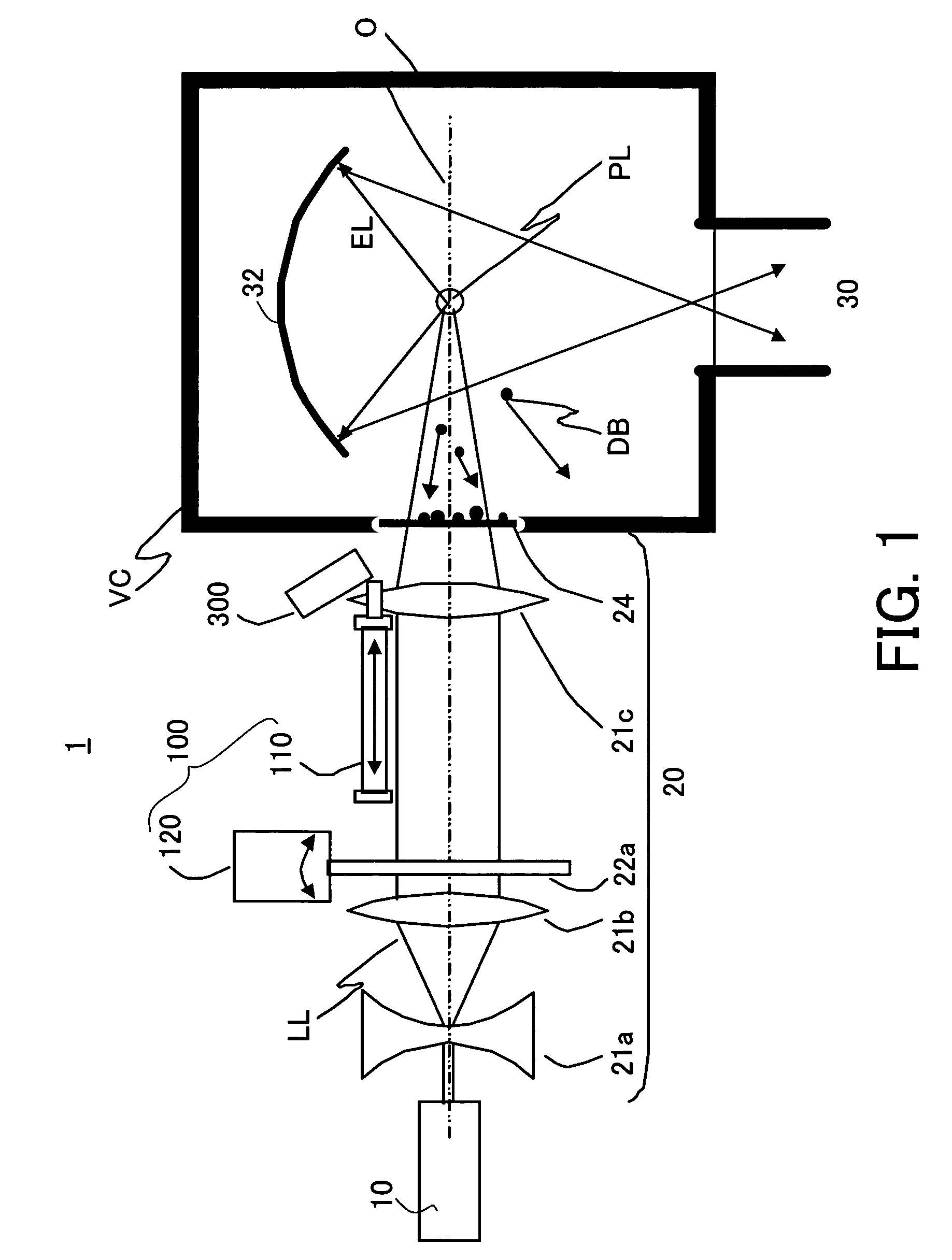
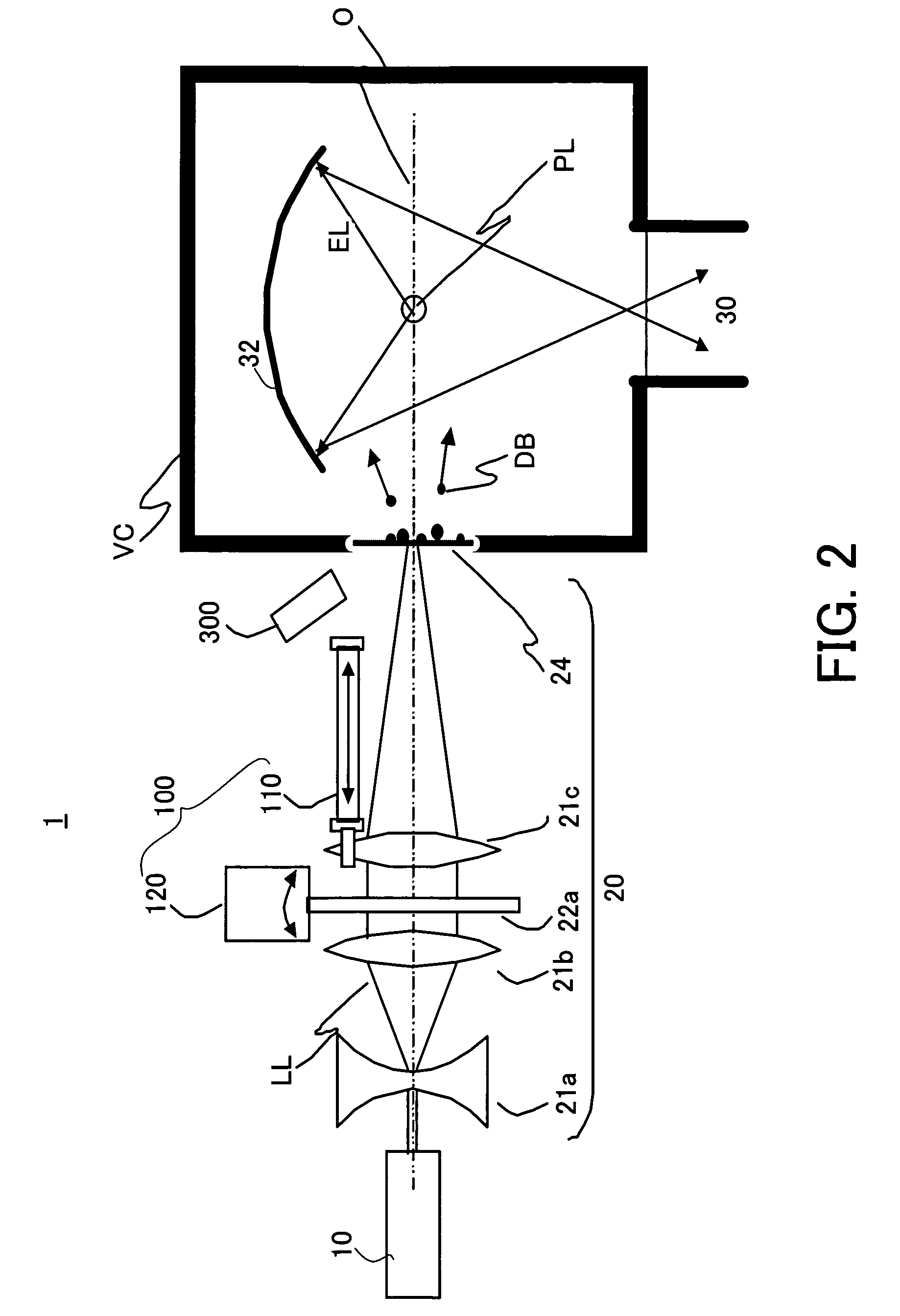
[0035]Referring now to the accompanying drawings, a description will be given of the preferred embodiments of the present invention. Like elements are designated by the same reference numerals, and a duplicate description will be omitted. FIG. 1 is a schematic block diagram of a structure of a light generator 1 according to one aspect of the present invention, showing an emitting state of the EUV light EL. FIGS. 2 and 3 are schematic diagrams of the structure of the light generator 1 according to one aspect of the present invention, which is removing debris DB from a laser introducing window 24.

[0036]The light generator 1 is one that irradiates the laser light LL onto a target, generates the plasma PL, and producing the EUV light EL from the plasma PL. The light generator 1 includes a laser light source section 10 that irradiates the laser light LL onto the target, a laser optical system 20 as a first optical system that introduces the laser light LL to the target, an EUV optical sy...


PUM

PropertyMeasurementUnit
wavelengthaaaaaaaaaa

Abstract

A light generator for irradiating a laser onto a target, for generating plasma, and for producing light from the plasma, includes a first optical system for introducing the light to the target, a second optical system for introducing the light, and a unit for irradiating the laser onto debris that attaches to at least one of the first and second optical systems by changing an irradiation condition of the laser differently from that used to generate the plasma.

Description

BACKGROUND OF THE INVENTION[0001]The present invention relates generally to a light generator, and more particularly to a light source used to transfer a fine pattern in the semiconductor manufacture. The present invention is suitable, for example, for an exposure apparatus that utilizes the X-ray and the extreme ultraviolet (“EUV”) light as a light source.[0002]A reduction projection exposure apparatus has been conventionally employed which uses a projection optical system to project a circuit pattern of a mask (reticle) onto a wafer, etc. to transfer the circuit pattern, in manufacturing such a fine semiconductor device as a semiconductor memory and a logic circuit in the photolithography technology.[0003]The minimum critical dimension to be transferred by the projection exposure apparatus or resolution is proportionate to a wavelength of the light used for exposure, and inversely proportionate to the numerical aperture (“NA”) of the projection optical system. The shorter the wave...

Claims


Application Information

Patent Timeline
Patent Type & Authority Patents(United States)
IPC IPC(8): H05H1/00G01J1/00G21G4/00H05H1/24G21K5/00A61N5/00G03F7/20G21G5/00G21K5/02G21K5/08H01J35/00H01L21/027H05G2/00
CPCG03F7/70916H05G2/001G03F7/70925
Inventor MASAKI, FUMITAROMIYAKE, AKIRA
Owner CANON KK
Why Eureka
Try Eureka