Discharge lamp lighting device and projector

a technology of lighting device and discharge lamp, which is applied in the direction of electric variable regulation, process and machine control, instruments, etc., can solve the problems of difficult viewing of bright portions by viewers, uneven brightness of screen, and flickering, so as to prevent the appearance of a stripe and prevent flicker

Inactive Publication Date: 2009-03-31
SEIKO EPSON CORP
View PDF14 Cites 24 Cited by
  • Summary
  • Abstract
  • Description
  • Claims
  • Application Information

AI Technical Summary

Benefits of technology

[0006]An advantage of some aspects of the invention is that it provides a high pressure discharge lamp lighting device capable of preventing flicker and preventing a stripe from occurring on a display screen and a projector including the same.
[0008]In the high pressure discharge lamp lighting device according to this aspect, preferably, the control unit adjusts the width and / or height of the current pulse according to the power supplied to the high pressure discharge lamp. According to the above-mentioned structure, the control unit performs constant power control on the high pressure discharge lamp and adjusts the width and / or height of the current pulse according to the power. Therefore, it is possible to stably generate an AC arc and prevent an excessively large amount of energy from being supplied to the electrodes in the high pressure discharge lamp. As a result, it is possible to prevent the electrodes in the high pressure discharge lamp from wearing off.
[0010]In the high pressure discharge lamp lighting device according to the above-mentioned aspect, preferably, the control unit superposes the current pulse on the second half of the pulse width of the driving current. According to the above-mentioned structure, the current pulse is superposed on the second half of the pulse width of the driving current, which makes it possible to effectively stabilize the discharge arc in the high pressure discharge lamp and to prevent flicker.
[0011]In the high pressure discharge lamp lighting device according to the above-mentioned structure, preferably, the control unit randomly superposes the current pulse on the second half of the pulse width of the driving current. According to the above-mentioned structure, since the current pulse is superposed on the second half of the pulse width of the driving current it is possible to effectively stabilize the discharge arc in the high pressure discharge lamp. Even when the high pressure discharge lamp lighting device is used for a projector, the position of the current pulse is not fixed, which makes it possible to prevent flicker on the display screen.

Problems solved by technology

When the lamp is used as, for example, a light source of a projector, the brightness on a screen increases for a time corresponding to the superposition of the current pulse on the lamp current, which is an adverse effect.
Since the current pulse is synchronously superposed on the lamp current, a partially bright portion is fixed at a predetermined position on the screen, which causes problems that the brightness on the screen is not uniform and a stripe occurs on the display screen.
Therefore, even when the high pressure discharge lamp lighting device is used for a projector, the current pulse causes a corresponding portion of the display screen to be bright, but the bright portion is not fixed, which makes it difficult for a viewer to view the bright portion.
As a result, the viewer cannot recognize the bright portion as a stripe on the display screen.
However, the current pulse is inserted into a different position of each frame of the display screen, and the bright position is not fixed, which makes it difficult for a viewer to view the bright portion.
As a result, the viewer cannot recognize the bright portion as a stripe on the display screen.

Method used


Image

  • Discharge lamp lighting device and projector
  • Discharge lamp lighting device and projector
  • Discharge lamp lighting device and projector

Examples


first embodiment

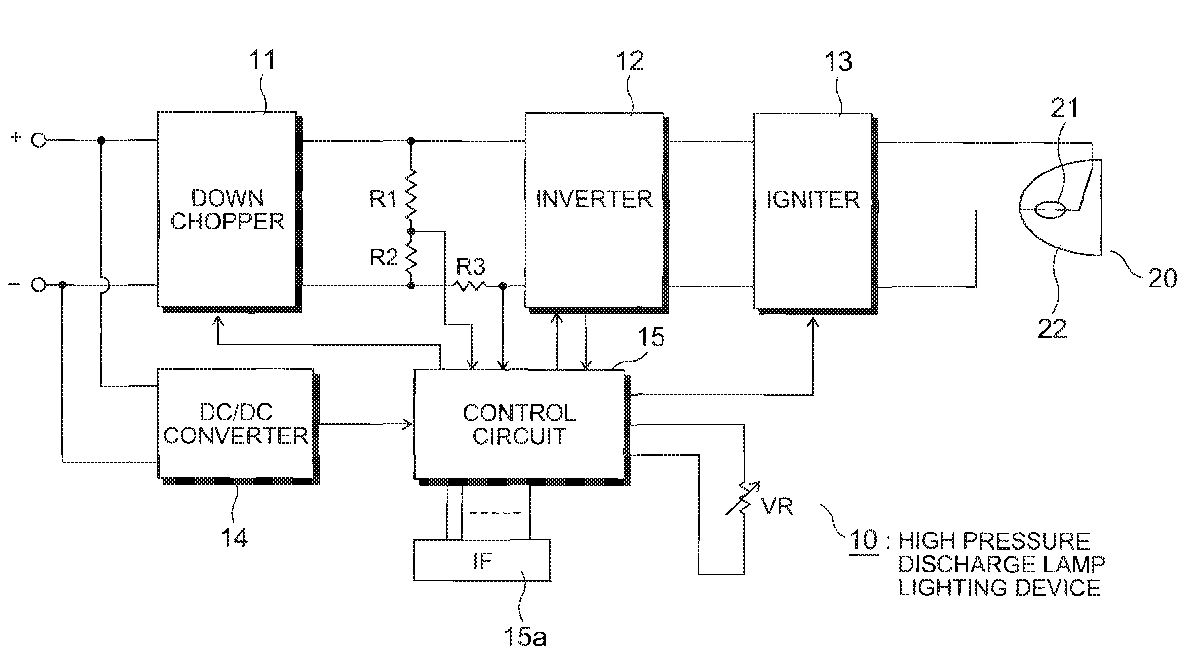
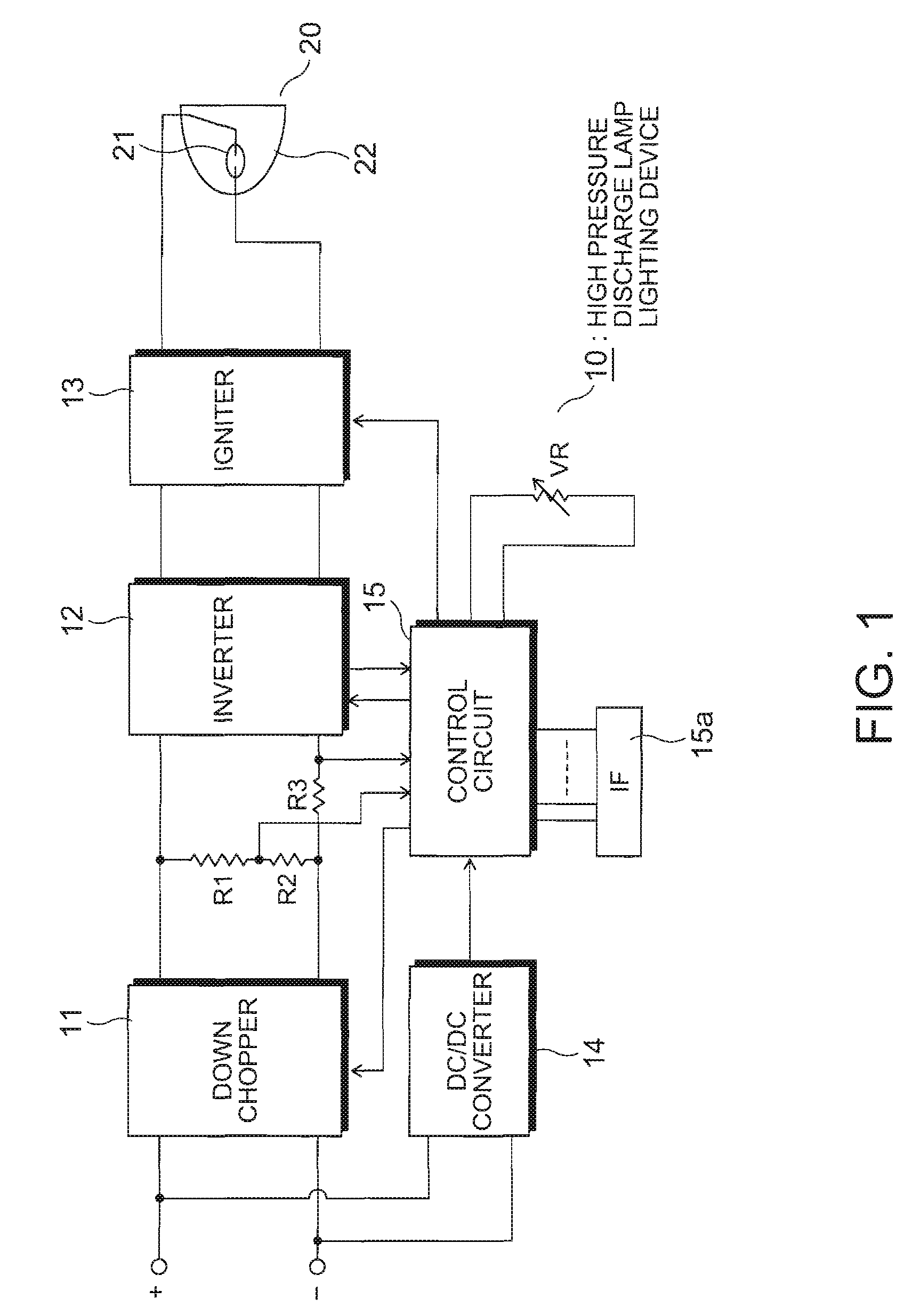
[0020]FIG. 1 is a block diagram illustrating the structure of a high pressure discharge lamp limiting device according to a first embodiment of the invention. The high pressure discharge lamp lighting device shown in FIG. 1 includes a down chopper 11, an inverter 12, an igniter 13, a DC / DC converter 14, and a control circuit 15. A lamp 20 is connected to output terminals of the igniter 13. The down chopper 11 corresponds to a DC power supply circuit according to the embodiment of the invention and adjusts an input DC voltage to supply a predetermined constant power to the lamp 20. In this embodiment, the down chopper 11 performs a chopper process on an input voltage to drop the input voltage and performs current control to supply a predetermined constant power to the lamp 20. A current output from the down chopper 11 is input to the inverter 12. Resistors R1 and R2 are connected in parallel to output terminals of the down chopper 11, and the potential of a node between the resistors...

second embodiment

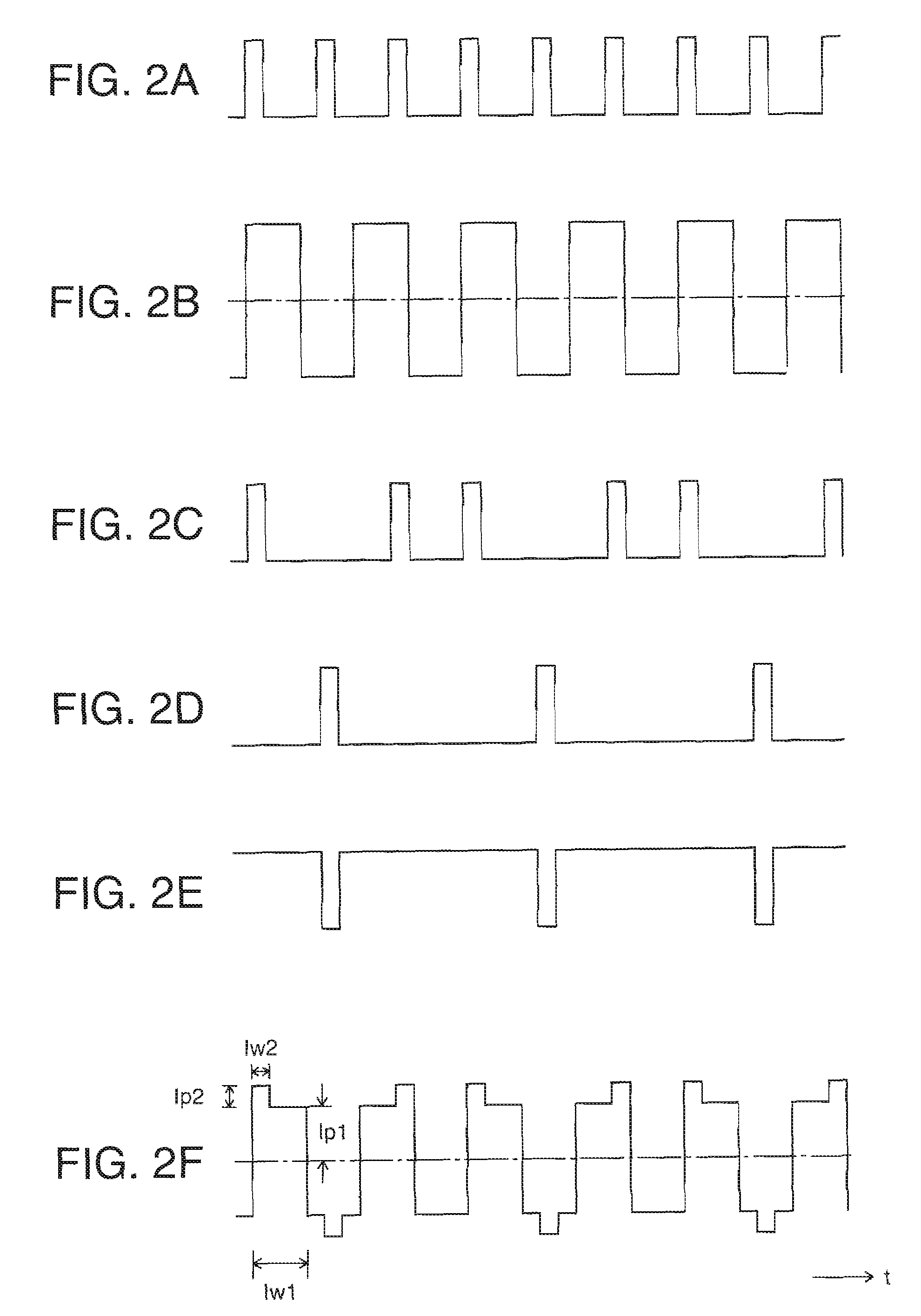
[0028]FIG. 4 is a timing chart illustrating another example of the signal waveforms for generating the lamp current shown in FIG. 1. In FIG. 4, the character G indicates a mask pattern. When pulses in pulse strings C and E are disposed at the first half of the pulse width of a lamp lighting waveform B, such pulses are masked by the mask pattern G. Only when pulses in the pulse strings C and E are disposed at the second half of the pulse width of the lamp lighting waveform B, such pulses are superposed on the lamp lighting waveform B. In this way, the pulse strings C and E are superposed on the second half of the pulse width of the lamp lighting waveform B to generate a lamp lighting waveform F. Since the position of the superposed pulse string is not fixed, the same effect as that in the first embodiment can be obtained. In addition, the current pulse is superposed on the second half of the pulse width of the lamp current, which makes it possible to stabilize the discharge arc of th...

third embodiment

[0029]FIG. 5 is a diagram illustrating the structure of an optical system of a protector, which is an assembly of the high pressure discharge lamp lighting device according to the first or second embodiment and an illustration optical system. A high pressure discharge lamp lighting device 10 shown in FIG. 5 corresponds to the high pressure discharge lamp lighting device 10 shown in FIG. 1. In this embodiment, the frequency of the superposed current pulse differs from the frequency of the driving current of the lamp 20 and the frequencies of vertical synchronization signals of liquid crystal display panels 250, 252, and 254.

[0030]The projector includes an illustration optical system 100, dichroic mirrors 210 and 212, reflecting mirrors 220, 222, and 224, an incident-side lens 230, a relay lens 232, three field lenses 240, 242, and 244, three liquid crystal display panels 250, 252, and 254, polarizing plates 251, 253, 255, 256, 257, and 258 arranged on the emission sides and the incid...


PUM


Abstract

A high pressure discharge lamp lighting device includes: a DC power supply circuit that is supplied with a DC voltage and performs current control to supply a predetermined constant power to a high pressure discharge lamp; an inverter that converts an output current of the DC power supply circuit into an AC current having a predetermined frequency and supplies a driving current to the high pressure discharge lamp; and a control unit that controls the DC power supply circuit and the inverter. In the high pressure discharge lamp lighting device, the control unit superposes a current pulse asynchronous with the driving current on the driving current.

Description

BACKGROUND[0001]1. Technical Field[0002]The present invention relates to a high pressure discharge lamp lighting device and a projector including the same, and more specifically, to a technique for preventing flicker.[0003]2. Related Art[0004]In the related art, for example, the following method is used in a high pressure discharge lamp lighting device used for a light source of a projector in order to stabilize the discharge arc in a high pressure discharge lamp (hereinafter, referred as a lamp): when an AC lamp current is supplied to a high pressure discharge lamp to turn on the high pressure discharge lamp, a current pulse having a period obtained by dividing half the period of the lamp current by a predetermined value is generated, the polarity of the current pulse becomes identical to the polarity of the lamp current, and a latter part of the half period of the current pulse is superposed on the lamp current (for example, JP-T-10-501919 (see claims and FIG. 4).[0005]In the rela...

Claims


Application Information

Patent Timeline
Patent Type & Authority Patents(United States)
IPC IPC(8): H05B37/02
CPCH05B41/2882H05B41/2928Y02B20/208Y02B20/00
Inventor OKAWA, KAZUO
Owner SEIKO EPSON CORP
Why Eureka
Try Eureka