Vehicular forward-vision display system decreasing luminance with decreasing vehicle speed

a technology of forward-vision display and luminance, which is applied in the direction of optical radiation measurement, identification means, color signal processing circuits, etc., can solve the problems of displaying various problems, unnecessary vision aids for displaying images located in a long distance, traffic accidents, etc., and achieve the effect of decreasing vehicle speed, reducing luminance intensity of displayed images, and reducing vehicle accidents

Inactive Publication Date: 2006-08-15
DENSO CORP
View PDF6 Cites 37 Cited by
  • Summary
  • Abstract
  • Description
  • Claims
  • Application Information

AI Technical Summary

Benefits of technology

[0010]It is an object of the present invention to provide a vehicular forward-vision display system where luminance of a displayed image is decreased when the displayed image becomes an offending item for a driver.
[0011]To achieve the above object, a vehicular forward-vision display system is provided with the following. A night-vision camera is disposed for scanning a nighttime image ahead of a vehicle. A displaying unit is disposed for displaying the scanned nighttime image as a virtual image on a front windshield. Here, luminance intensity of the d

Problems solved by technology

This invisibility of the nighttime image may lead to a traffic accident.
However, constantly maintaining the luminance of the displayed image results in exhibiting various problems.
At a low speed, the vision a

Method used


Image

  • Vehicular forward-vision display system decreasing luminance with decreasing vehicle speed
  • Vehicular forward-vision display system decreasing luminance with decreasing vehicle speed
  • Vehicular forward-vision display system decreasing luminance with decreasing vehicle speed

Examples


first embodiment

[0023](First Embodiment)

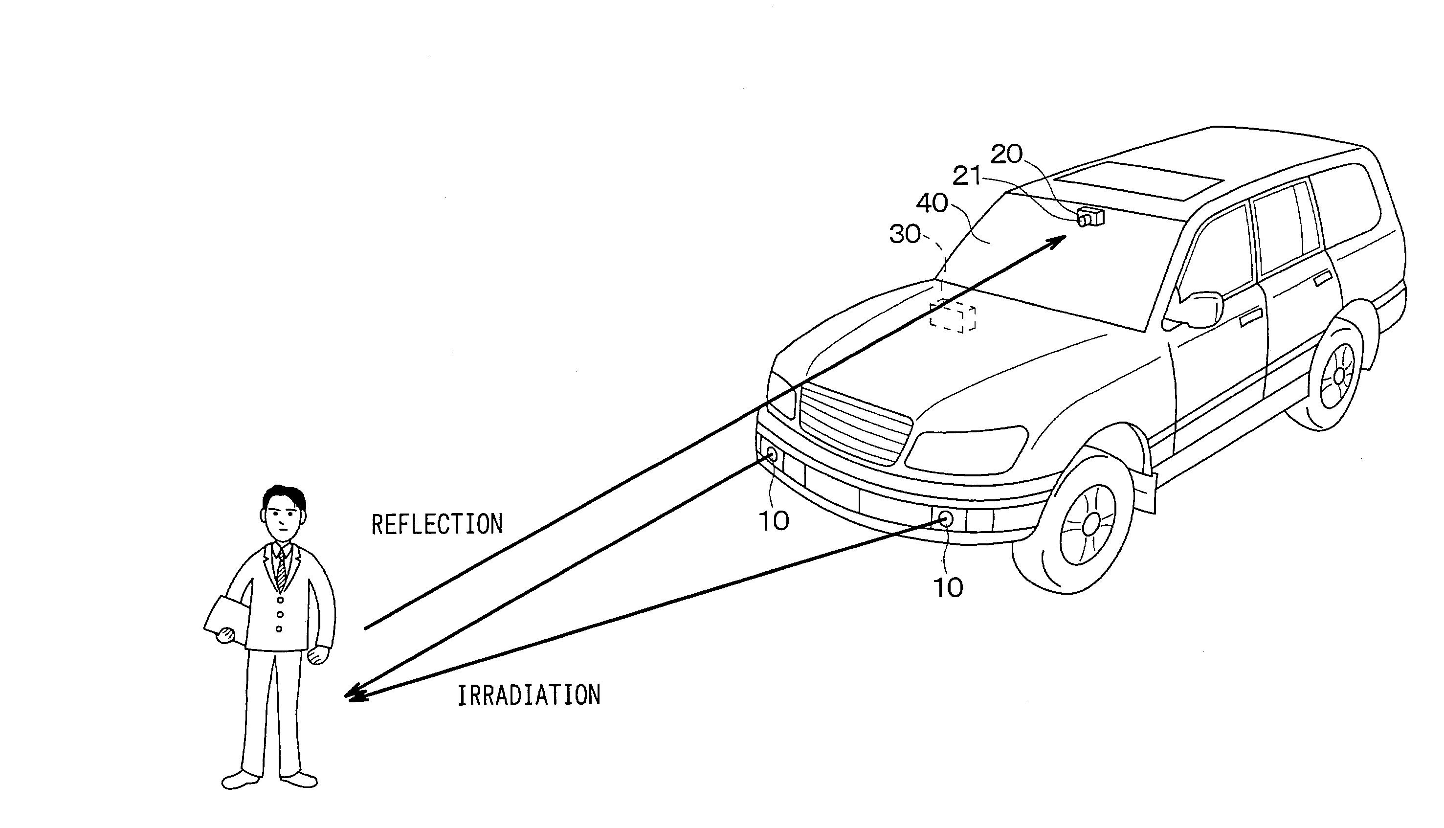
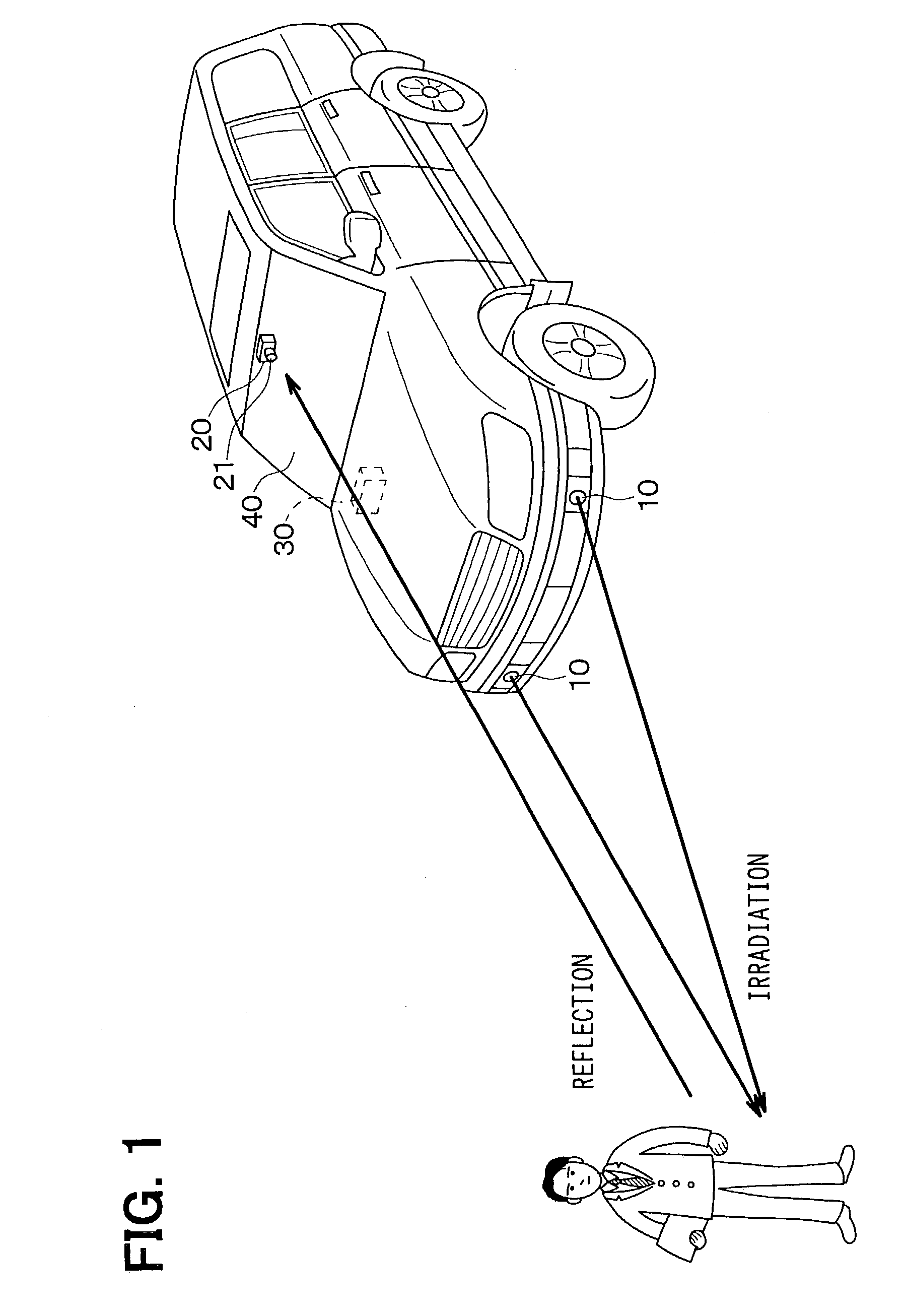
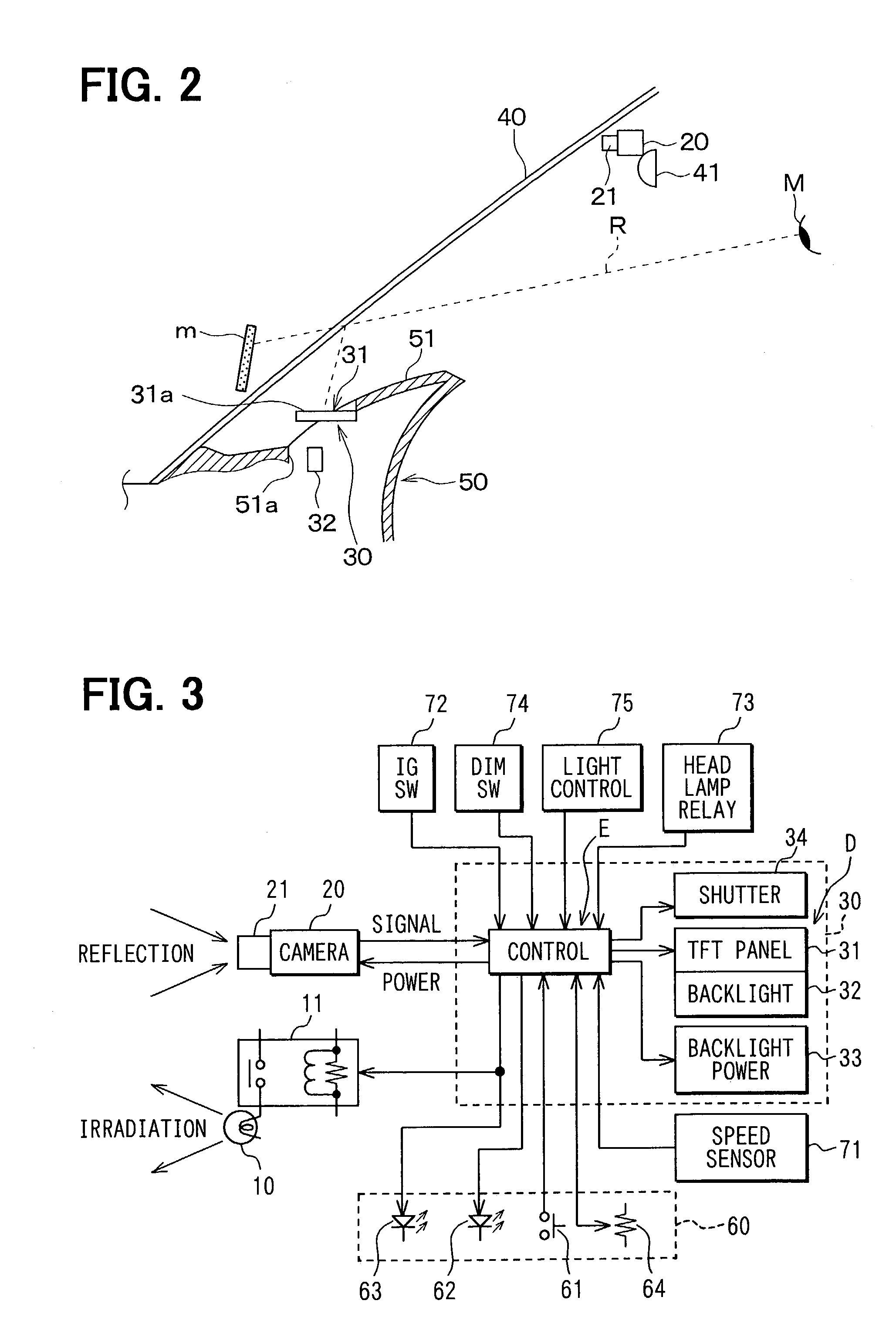
[0024]A vehicular forward-vision display system as a first embodiment of the present invention is directed to a passenger vehicle shown in FIG. 1. The system includes infrared lamps 10 for irradiating a nighttime image ahead of the vehicle by infrared light, a night-vision camera 20 for scanning the nighttime images irradiated by the infrared light, and a head-up display 30 as a displaying device for displaying the scanned images on a front windshield 40 of the vehicle.

[0025]The infrared lamps 10 irradiate near-infrared light having a range of wave length between 800 nm and 1000 nm and are disposed under headlights in front of the vehicle.

[0026]The night-vision camera 20 is a known infrared camera that has a telephoto lens 21 and scans an image by accumulating static electricity in proportion to received infrared. The infrared camera 20 is disposed near an upper side of the windshield 40 in an interior of the vehicle and in a rear side of a rearview mirror 41...

second embodiment

[0056](Second Embodiment)

[0057]In a second embodiment, the luminance intensity of the displayed image is stepwise varied by determining whether the vehicle speed is higher than a predetermined speed, while it is varied gradually according to the vehicle speed in the first embodiment. In detail, luminance intensity of the displayed image is determined as shown in FIGS. 7 and 8.

[0058]At Step 120 in FIG. 7, whether the vehicle speed is increasing is determined. When the vehicle speed is determined to be increasing, whether the vehicle speed is lower than a predetermined speed V3 is determined at Step 131. When the vehicle speed is determined to be lower than the predetermined speed V3 (V3), the luminance intensity is determined to be the lowest value (MIN) at Step 141. When the vehicle speed is determined to be not lower than the predetermined speed V3 (V≧V3), the luminance intensity is determined to be the highest value (MAX) at Step 161.

[0059]By contrast, when the vehicle speed is de...


PUM


Abstract

A vehicular forward-vision display system includes a night-vision camera for scanning a nighttime image ahead of a vehicle and a head-up display for displaying the scanned nighttime image as a virtual image on a front windshield. Luminance of the displayed image is decreased with decreasing vehicle speed. The luminance of the nighttime image is thereby decreased under a low speed where vision aid is not so necessary. This decreasing of the luminance results in giving a driver relief from the bother of being caught by the scanned image displayed on the front windshield.

Description

CROSS REFERENCE TO RELATED APPLICATIONS[0001]This application is based on and incorporates herein by reference Japanese Patent Application No. 2002-219849 filed on Jul. 29, 2002.[0002]1. Field of the Invention[0003]The present invention relates to a vehicular forward-vision display system for scanning a nighttime image ahead of a vehicle and for displaying the scanned image as a virtual image on a front windshield. In particular, luminance of the displayed image is decreased with decreasing vehicle speed.[0004]2.Backgroud of the Invention[0005]At night, an image in a nighttime dark area cannot be visible by a naked eye of a driver in a long distance where headlights of a vehicle cannot reach (e.g., about 100 to 400 m ahead of a vehicle). This invisibility of the nighttime image may lead to a traffic accident.[0006]A vehicular forward-vision display system is proposed in JP-A-H6-107036 for assisting safe driving by providing vision aid for nighttime vision of a driver. In the system,...

Claims


Application Information

Patent Timeline
IPC IPC(8): H04N7/18B60K35/00B60R1/00G02B23/12G02B27/00G02B27/01G09F19/12G09G5/00G09G5/10
CPCB60R1/00G02B23/12G02B27/01G02B27/0101B60R2300/103B60R2300/106B60R2300/205B60R2300/302G02B2027/0138G02B2027/0118B60R2300/8053
Inventor EGUCHI, SHOTAROSENOO, HIDEKITAKAGI, HIROKAZUHIRAYAMA, YASUOGOTO, YOSHIHIKO
Owner DENSO CORP
Why Eureka
Try Eureka