
Air-directing unit

a technology of air-directing units and air-directing connectors, which is applied in the direction of electrical apparatus casings/cabinets/drawers, semiconductor/solid-state device details, coupling device connections, etc., can solve the problems of inability to effectively cool down the installed memory modules, degradation of the electrical connection between the subsequently installed memory modules and the connector, and not always feasible solutions

Active Publication Date: 2006-08-15
HEWLETT-PACKARD ENTERPRISE DEV LP
View PDF4 Cites 16 Cited by
  • Summary
  • Abstract
  • Description
  • Claims
  • Application Information

AI Technical Summary

Benefits of technology

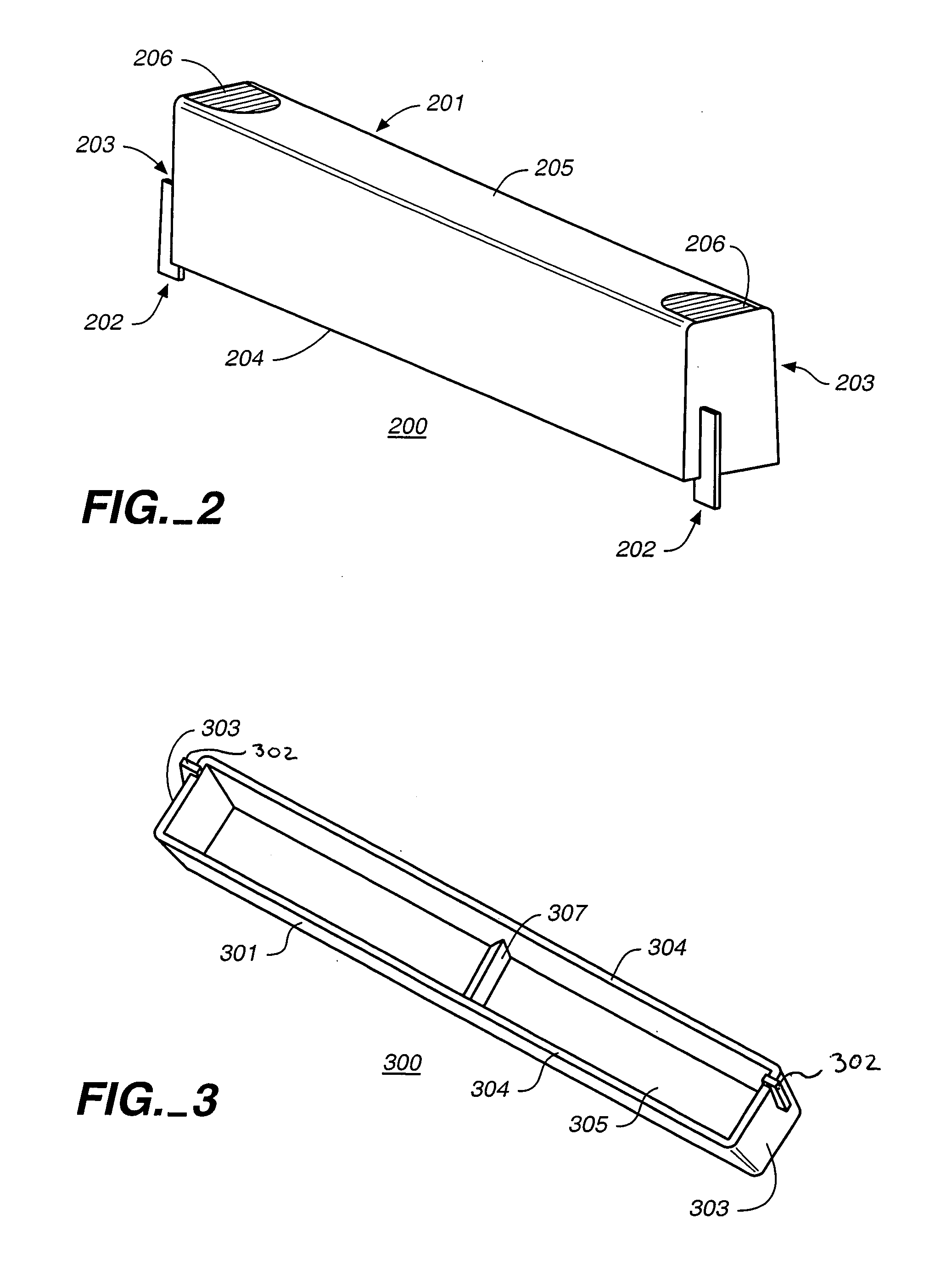
[0010]The present invention is an air-directing unit for use in redirecting air flow in a memory module environment of a computer. The air-directing unit comprises a body portion configured to redirect air flow therearound such that the air flow is redirected in the memory module environment. Additionally, the air-directing unit includes a coupling element for removably engaging the air-directing unit with a connector portion of the memory module environment, the coupling element removably engaging the air-directing unit without compromising electrical contacts in the connector.

Problems solved by technology

However, if the installed modules are crowded together and / or if they are located in inaccessible areas in the memory environment, the cooling air will tend to take a path of least resistance and pass over the unoccupied space, instead of passing by the installed memory modules.
Consequently, the installed memory modules are not effectively cooled.
A problem with this solution is that since the dummy module or the plastic sheet, when inserted in the connector, rubs the contacts, the contacts prematurely wear and / or accumulate debris and film, causing degradation of the electrical connection between the subsequently installed memory modules and the connector.
However, this solution is not always feasible due to lack of available space in the memory module environment to accommodate the sheet metal.
Besides, this solution tends to be relatively expensive as the sheet metal has to be customized for each environment.
However, this solution also is not always feasible if the design requires that the modules are clustered together.

Method used


Image

  • Air-directing unit
  • Air-directing unit
  • Air-directing unit

Examples


Embodiment Construction

[0017]Reference is now made in detail to embodiments of the present invention, examples of which are illustrated in the accompanying Figures. While the invention is described in conjunction with these embodiments, it is to be understood that the invention is not limited to these embodiments. On the contrary, the invention is intended to cover alternatives, modifications and equivalents which are included within the spirit and scope of the invention as defined by the appended claims. Furthermore, in the following description of the invention, numerous specific details are set forth in order to provide a thorough understanding of the present invention. However, it will be understood by those of ordinary skill in the art that the present invention may be practiced without these specific details. In other instances, it will be understood that it is not necessary to describe in detail, well-known methods, procedures, components, and circuits to avoid unnecessarily obscuring aspects of th...


PUM


Abstract

An air-directing unit for use in redirecting air flow in a memory module environment of a computer. The air-directing unit comprises a body portion configured to redirect air flow therearound such that the air flow is redirected in the memory module environment. The air-directing unit includes a coupling element for removably engaging the air-directing unit with a connector portion of the memory module environment, the coupling element removably engaging the air-directing unit without compromising electrical contacts in the connector.

Description

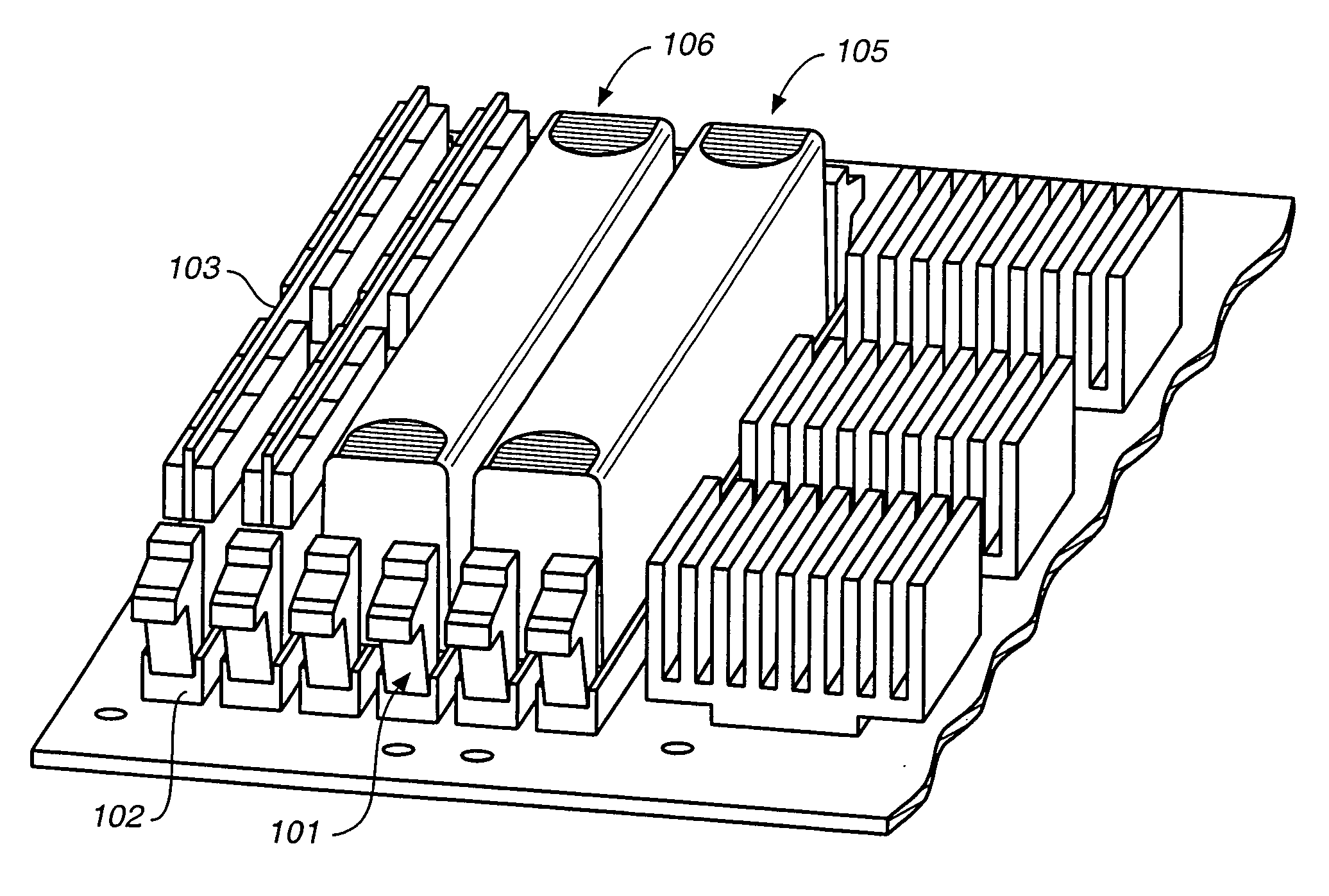
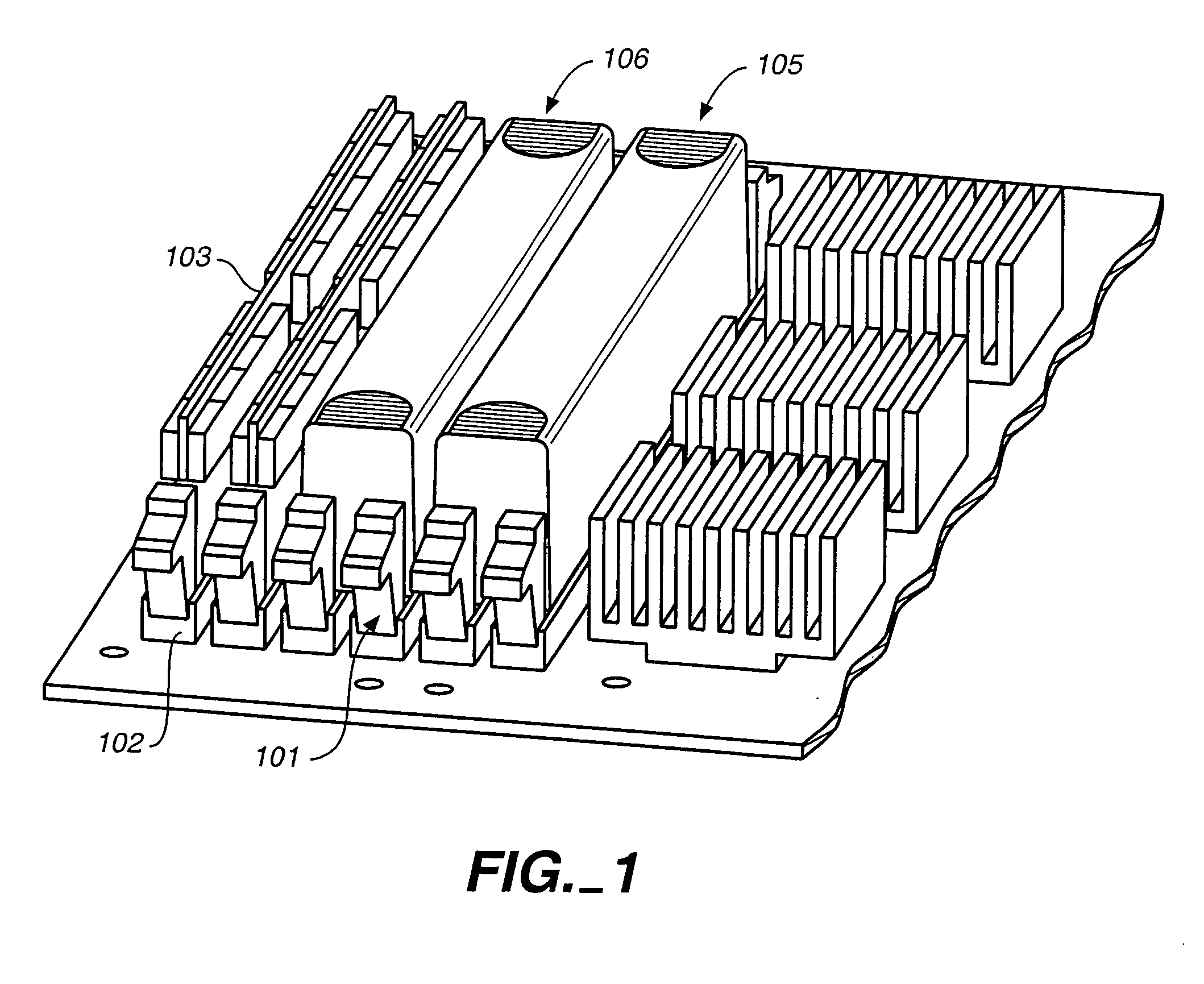
TECHNICAL FIELD[0001]The present invention pertains to an air-directing unit for redirecting air flow in a memory module environment of a computer.BACKGROUND ART[0002]In the memory module environment of a computer, electro-mechanical connectors, referred to as “connectors”, are used to accommodate memory modules and establish an electrical connection between the memory module and other computer system components. A memory module is a collection of memory chips e.g. DRAMs mounted on a single substrate or a small printed circuit board. As is illustrated schematically in FIG. 1, a connector 101 typically comprises a mating portion 102 into which the memory module 103 is removably insertable to establish the electrical connection. The portion of the connector wherein the electrical connection is made is referred to as the “contact”.[0003]A single memory module 103 when inserted in the connector 101 is referred to as a “single in-line memory module” (“SIMM”). A SIMM is a memory module wi...

Claims


Application Information

Patent Timeline
Patent Type & Authority Patents(United States)
IPC IPC(8): H05K7/20G06F1/20H01L23/467
CPCG06F1/20H01L23/467H01L2924/0002H01L2924/00
Inventor ROBERTSON, KENNETH G.
Owner HEWLETT-PACKARD ENTERPRISE DEV LP
Learn More