Fuser and intermediate transfer drums

a transfer drum and drum body technology, applied in the field of printers or copiers, can solve the problems of substantial amounts of vapor in the drum at high temperature and pressur

Inactive Publication Date: 2006-08-15
HEWLETT PACKARD INDIGO BV
View PDF37 Cites 7 Cited by
  • Summary
  • Abstract
  • Description
  • Claims
  • Application Information

AI Technical Summary

Benefits of technology

[0019]It is an object of some embodiments of the invention to provide an intermediate transfer member or fuser of modified design and performance.

Problems solved by technology

However, in order to perform these functions, substantial amounts of vapor at high temperature and pressure are present in the drum.
This may cause a hazard if the drum fails.

Method used


Image

  • Fuser and intermediate transfer drums
  • Fuser and intermediate transfer drums
  • Fuser and intermediate transfer drums

Examples


Embodiment Construction

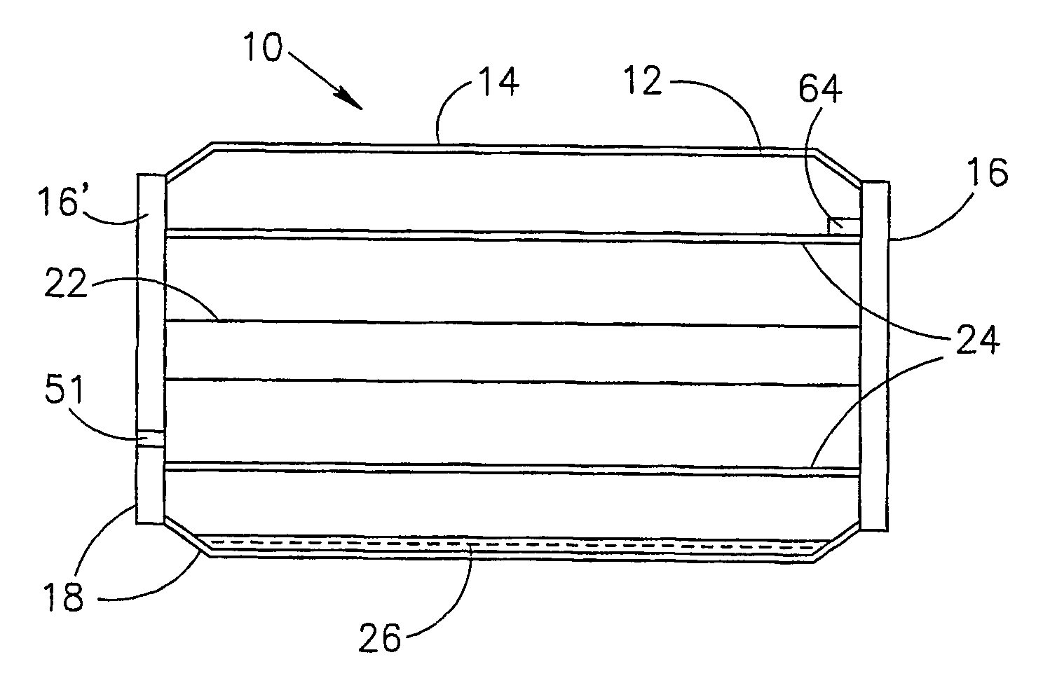
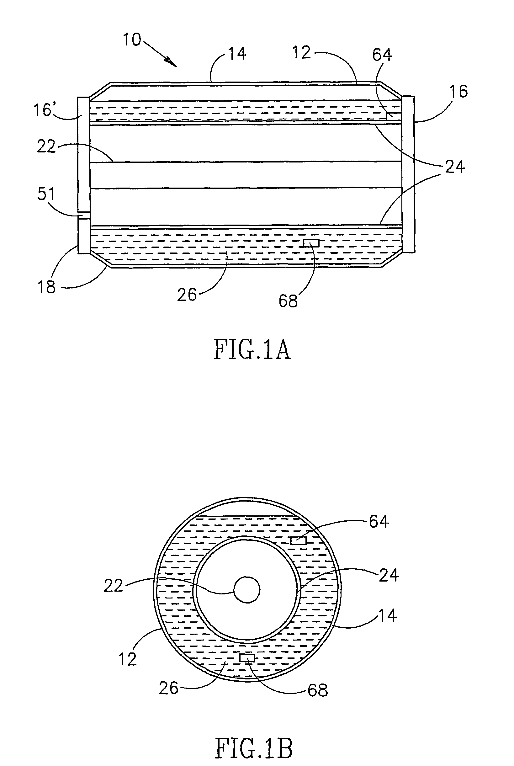
[0091]Reference is now made to FIGS. 1A and 1B which respectively show longitudinal and trans-axial cross-sectional illustrations of an intermediate transfer member 10, in accordance with an exemplary embodiment of the present invention. Intermediate transfer member 10, as shown, comprises:[0092]a) A cylindrical drum 18, comprising a membrane 12 of about 50 to about 250 micrometers thickness, typically about 125 micrometers, to which an intermediate transfer blanket 14 is mounted or adhered. The membrane may be made of a metal. The membrane is shown as having a bend near its ends. However, the membrane may be formed as a simple cylinder.[0093]b) Intermediate transfer blanket 14 (or optionally a suitable multi-layer coating on drum 18). In some embodiments of the invention, no blanket is used, although it is usually desirable to provide at least a non-stick coating on the membrane.[0094]c) Two end plates, 16 and 16′, on which membrane 12 is mounted and attached, by soldering, welding...


PUM


Abstract

Apparatus for transferring visible images from a first surface to a second surface and/or for fusing or fixing a visible image to a substrate, comprising: a cylindrical member secured between two round end plates to form a cylindrical structure; a volatile liquid incorporated within the cylindrical structure in a cavity, at least one wall of which is thermally connected to the cylindrical member; and a heater that heats the liquid to an operating temperature, wherein the amount of the volatile liquid is such that all of the volatile liquid would be evaporated at a temperature that is less than about 20° C. above the operating temperature.

Description

RELATED APPLICATIONS[0001]The present application is a U.S. national application of PCT Application No. PCT / IL00 / 00652, filed on Oct. 13, 2000.FIELD OF THE INVENTION[0002]The present invention is related to the field of printers and copiers and more particularly to printers or copiers that utilize fusers, intermediate transfer members and / or elements that function as both fusers and intermediate transfer members.BACKGROUND OF THE INVENTION[0003]Printers and copiers are well known. Modern copiers that utilize powder or liquid toners comprising toner particles to form visible images generally form a latent electrostatic image on an image forming surface (such as a photoreceptor), develop the image utilizing a toner (such as the aforementioned powder or liquid toners) to form a developed image and transfer the developed image to a final substrate. The transfer may be direct, i.e., the image is transferred directly to the final substrate from the image forming surface, or indirect, i.e....

Claims


Application Information

Patent Timeline
Patent Type & Authority Patents(United States)
IPC IPC(8): G03G15/20G03G15/16G03G15/22G03G15/24H05B3/00
CPCG03G15/161G03G15/22G03G15/2053G03G2215/1685
Inventor LANDA, BENZIONLAVON, AMIRANSCHNEIDER, AVNERROMEM, ILAN
Owner HEWLETT PACKARD INDIGO BV
Why Eureka
Try Eureka