Power supply control device and image forming apparatus

a technology of power supply control device and image forming apparatus, which is applied in the direction of electrical apparatus, electrographic process apparatus, instruments, etc., can solve the problems of low electrical resistance of halogen heater, high inrush current of halogen heater, voltage drop, etc., and achieve the effect of prolonging the warm-up time and suppressing the flow of inrush curren

Active Publication Date: 2018-11-13
KONICA MINOLTA INC
View PDF14 Cites 0 Cited by
  • Summary
  • Abstract
  • Description
  • Claims
  • Application Information

AI Technical Summary

Benefits of technology

[0015]In view of such problems, the present invention aims to provide a power supply control device and an image forming apparatus that suppress inrush current flowing upon cold start of a halogen heater without extending warm-up time.

Problems solved by technology

However, halogen heaters may be problematic for inducing high inrush current, particularly immediately after they are turned on from a cold state (an off state with low halogen heater temperature).
This is because halogen heaters have low electrical resistance in the cold state.
The flow of high inrush current through a halogen heater results in voltage drop of a power supply line connected to the halogen heater and increases the risk of consequent problems such as flickering of fluorescent lamps connected to the power supply line.
Further, particularly when a step-down chopper circuit connected to a halogen heater includes an insulated gate bipolar transistor (IGBT) with low withstand voltage, turning on the halogen heater in the cold state (referred to in the following as a cold start of a halogen heater) at a high duty cycle may result in destruction of the IGBT.
While IGBT destruction by inrush current can be prevented by using an IGBT with high withstand voltage, this measure is not practical because the use of an IGBT with high withstand voltages is costly.
However, the longer the reduced duty cycle is used, the longer the warm-up time of the halogen heater.
However, with the conventional technology described above, input voltage is always restricted for a predetermined amount of time every time the halogen lamp is turned on, and due to this, a long amount of time is always required for startup.
That is, applying the conventional technology described above to an image forming apparatus results in an extension in the amount of time required for warm up and a consequent extension in FCOT, due to the conventional technology requiring restricting input voltage for a certain amount of time.

Method used


Image

  • Power supply control device and image forming apparatus
  • Power supply control device and image forming apparatus
  • Power supply control device and image forming apparatus

Examples


Embodiment Construction

[0027]The following embodiment describes a form of implementation of the power supply control device and the image forming apparatus pertaining to the present invention, with reference to the accompanying drawings.

[1] Structure of Image Forming Apparatus

[0028]The following describes the structure of the image forming apparatus pertaining to the present invention.

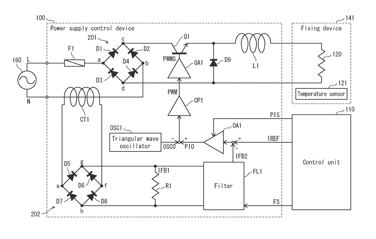
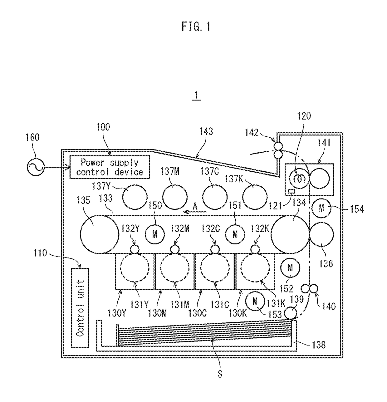
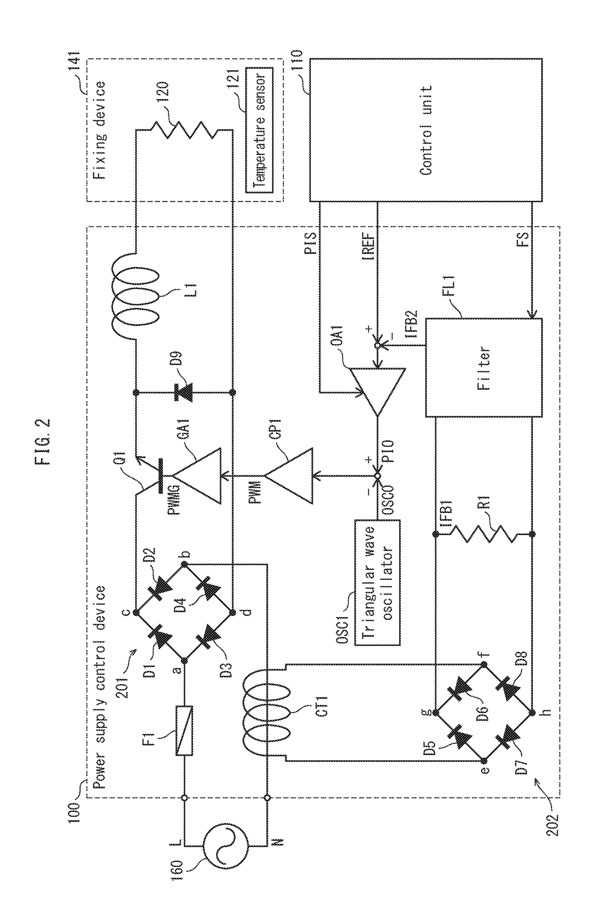
[0029]FIG. 1 illustrates an image forming apparatus 1, which is one form of implementation of the image forming apparatus pertaining to the present invention. The image forming apparatus 1 is a color printer having the tandem system, and includes a power supply control device 100. The power supply control device 100 is a low voltage power supply, and receives AC power from an external power source 160 and supplies various components of the image forming apparatus 1 with power. For example, the power supplied by the power supply control device 100 is used for driving and controlling various components of the image forming app...


PUM


Abstract

A power supply control device including a chopper circuit generating a heater current for a halogen heater, a current feedback circuit generating a current feedback signal indicating a current amount based on an amount of the heater current, and a constant current circuit performing pulse-width modulation of the heater current amount according to a difference between a target heater current amount and the current amount indicated by the current feedback signal. The current feedback circuit switches between methods at least including a first method and a second method for generating the current feedback signal. The current feedback signal indicates a greater current amount with the first method than with the second method, and the current feedback circuit uses the first method during a period with a predetermined time length starting from when the halogen heater is turned on, and uses the second method after elapse of the period.

Description

CROSS-REFERENCE TO RELATED APPLICATIONS[0001]This application is based on application No. 2016-048914 filed in Japan, the contents of which are hereby incorporated by reference.BACKGROUND[0002](1) Technical Field[0003]The present invention is related to power supply control devices and image forming apparatuses. Specifically, the present invention is related to a technology of preventing destruction of a power supply control device upon cold start without extended warm-up time.[0004](2) Description of the Related Art[0005]Image forming apparatuses utilizing electrophotography have heat sources for heat-fixing toner onto recording sheets. Among various types of such heat sources, halogen heaters are widely used for achieving low cost. Fast switching of power supply to halogen heaters can be achieved by using step-down chopper circuits.[0006]However, halogen heaters may be problematic for inducing high inrush current, particularly immediately after they are turned on from a cold state...

Claims


Application Information

Patent Timeline
Patent Type & Authority Patents(United States)
IPC IPC(8): H05B1/02G03G15/00G03G15/20
CPCG03G15/205G03G15/80G03G15/2039
Inventor AOKI, MIKIYUKIKIRIKUBO, SEIICHIKIMURA, TAKUKIMATA, AKINORITAMADA, TAKESHI
Owner KONICA MINOLTA INC
Why Eureka
Try Eureka