
Method and apparatus for timing modeling

Active Publication Date: 2006-08-15
XILINX INC
View PDF86 Cites 9 Cited by
  • Summary
  • Abstract
  • Description
  • Claims
  • Application Information

AI Technical Summary

Problems solved by technology

This type of analysis is difficult at the outset, and is made more difficult by an embe

Method used


Image

  • Method and apparatus for timing modeling
  • Method and apparatus for timing modeling
  • Method and apparatus for timing modeling

Examples


Example

DETAILED DESCRIPTION OF THE DRAWINGS

[0020]In the following description, numerous specific details are set forth to provide a more thorough understanding of the present invention. However, it will be apparent to one of skill in the art that the present invention may be practiced without one or more of these specific details. In other instances, well-known features have not been described in order to avoid obscuring the present invention.

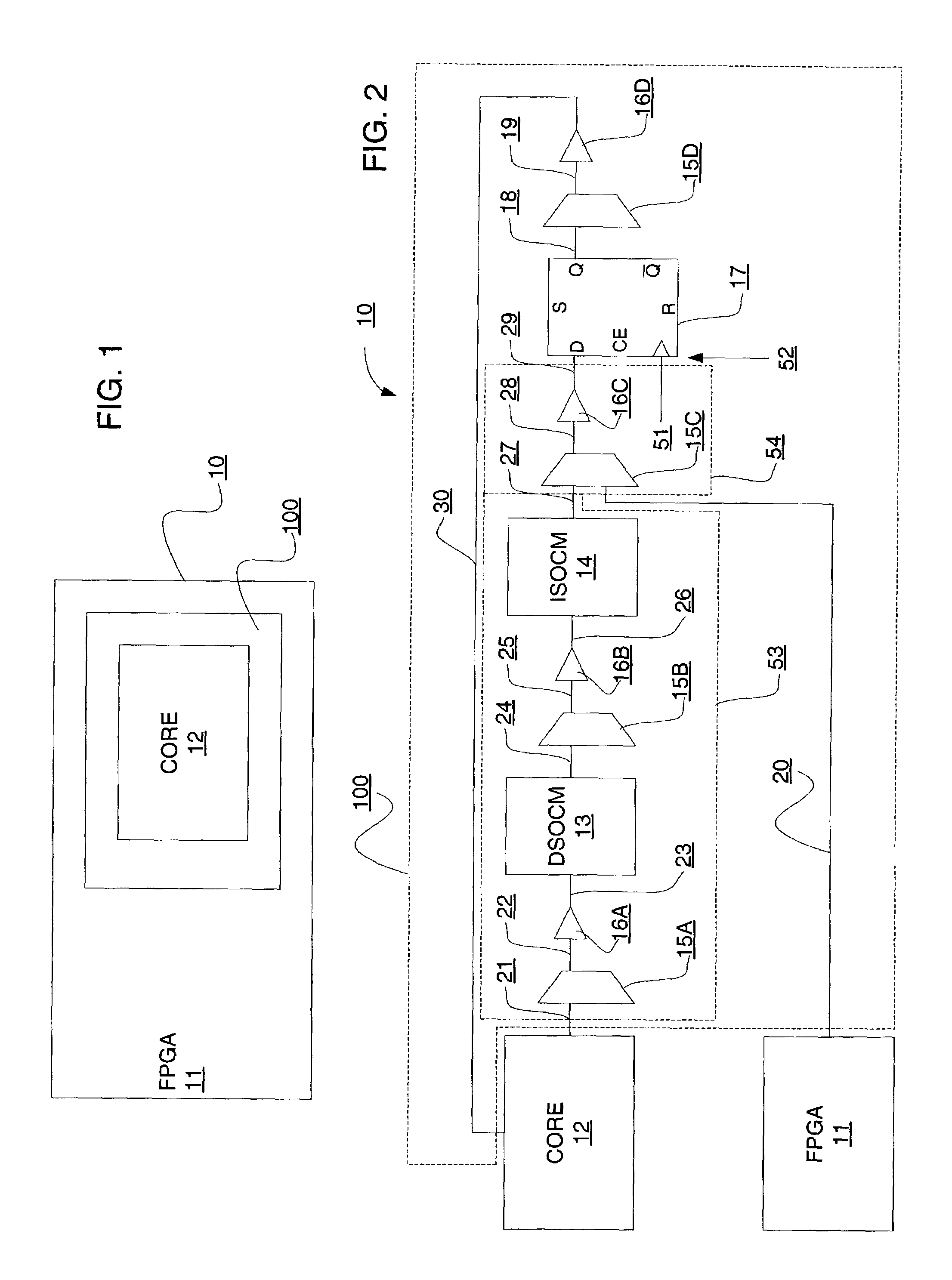
[0021]Referring to FIG. 1, there is shown a block diagram of an exemplary embodiment of an integrated circuit 10 in accordance with one or more aspects of the present invention. Integrated circuit 10 comprises a host device 11, a gasket module 100 and an embedded device 12. Gasket module 100 is for coupling embedded device 12 and host device 11. Examples of embedded device 12 include, but are not limited to, one or more microprocessors, microcontrollers, and digital signal processors, and examples of host device 11 include, but are not limited to, CPL...


PUM


Abstract

Method and apparatus for timing modeling is described. More particularly, sub-processes for obtaining timing information are described. Each of these sub-process is limited to a portion of a gasket module for coupling an embedded device to a host device, and each of these sub-process may be limited to a lithographic process dimension or adjusted accordingly. By dividing timing information gathering into sub-process, output from each of the sub-process may be combined with timing information provided with an embedded core to determine path delays.

Description

FIELD OF THE INVENTION[0001]The present invention relates generally to timing modeling, and more particularly to timing modeling for a gasket module for coupling a core embedded in a programmable logic device.BACKGROUND OF THE INVENTION[0002]Programmable logic devices exist as a well-known type of integrated circuit that may be programmed by a user to perform specified logic functions. There are different types of programmable logic devices, such as programmable logic arrays (PLAs) and complex programmable logic devices CPLDs). One type of programmable logic devices, called a field programmable gate array (FPGA), is very popular because of a superior combination of capacity, flexibility, time to market and cost.[0003]An FPGA typically includes an array of configurable logic blocks (CLBs) surrounded by a ring of programmable input / output blocks (IOBs). The CLBs and IOBs are interconnected by a programmable interconnect structure. The CLBs, IOBs, and interconnect structure are typical...

Claims


Application Information

Patent Timeline
IPC IPC(8): G06F17/50G06F9/45
CPCG06F17/5031G06F17/5027G06F30/3312G06F30/331
Inventor BURNLEY, RICHARD P.ODA, SHIZUKAGAN, ANDY H.
Owner XILINX INC
Features
  • Generate Ideas
  • Intellectual Property
  • Life Sciences
  • Materials
  • Tech Scout
  • Unparalleled Data Quality
  • Higher Quality Content
  • 60% Fewer Hallucinations
Learn More