Prefetch appliance server

a technology of appliance server and server, applied in the field of prefetch appliance server, can solve the problems of increasing complexity in the management of large capacity storage region, shortening the execution time of dbms's processing, and complicated management of information equipmen

Inactive Publication Date: 2006-08-15
HITACHI LTD
View PDF28 Cites 22 Cited by
  • Summary
  • Abstract
  • Description
  • Claims
  • Application Information

AI Technical Summary

Problems solved by technology

Furthermore, when data is divided among a plurality of physical storage devices, each of the physical storage devices can be accessed in parallel, which can further shorten the execution time for DBMS's processing.
As a result of this, however, various problems have arisen, such as increasingly complicated management of large capacity storage regions, increasingly complicated management of information equipment due to dispersed installation locations of storage devices and servers, and concentration of load on certain storage devices.
Technologies in the first through third documents described above improve performance by linking the DBMS processing with storage devices, but they are not designed to work in the virtualization environment.

Method used


Image

  • Prefetch appliance server
  • Prefetch appliance server
  • Prefetch appliance server

Examples


first embodiment

[0035]Referring to FIG. 1 through FIG. 14, the first embodiment is described.

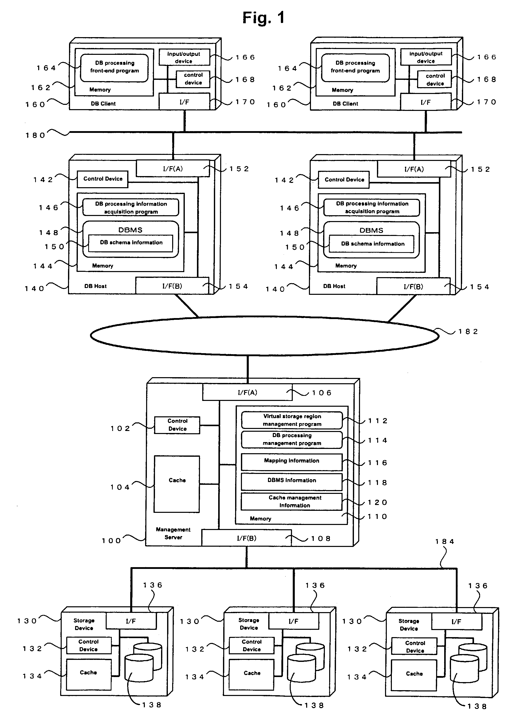
[0036]FIG. 1 is a diagram of a computer system to which the first embodiment of the present invention is applied.

[0037]The system of the present embodiment includes a management server 100, storage devices 130, DB hosts 140, DB clients 160, a network 184 that connects the management server 100 with the storage devices 130, a network 182 that connects the management server 100 with the DB hosts 140, and a network 180 that connects the DB hosts 140 with the DB clients 160.

[0038]Data communication between the management server 100 and the storage devices 130 takes place via the network 184. Data communication between the management server 100 and the DB hosts 140 takes place via the network 182. Data communication between the DB hosts 140 and the DB clients 160 takes place via the network 180. In the present system, the DB clients 160, the DB hosts 140 and the storage devices 130 may each be singular or plural...

second embodiment

[0127]Next, a system in accordance with the present invention will be described.

[0128]FIG. 15 is a diagram of an example of the system configuration according to the second embodiment of the present invention. It differs from the system configuration of the first embodiment in that there is no cache 104 or cache management information 120 in the management server 100, and that a network 186, as well as an I / F (B) 137 in each storage device 130, has been added to directly connect the storage devices 130 with (i.e., instead of via a management server 100) a network 182.

[0129]Of the processing described for the first embodiment, the processing that concerns cache processing in the management server 100 is omitted from the processing that takes place in the second embodiment. A DB processing management program 114 determines data that will be read in the near future based on DBMS information 118, issues an on-cache command 700 to the storage devices 130 that store the data to be read, a...

third embodiment

[0131]Next, a system in accordance with the present invention will be described.

[0132]The system according to the third embodiment is a system in which the cache 134 has been removed from each of the storage devices 134 in the system configuration according to the first embodiment. According to the third embodiment, there may be storage devices 130 with caches 134 and storage devices 130 without caches 134 within a single system.

[0133]Of the processing described for the first embodiment, the processing part in which a management server 100 issues the on-cache command 700 to the subordinate storage devices 130 is omitted from the processing that takes place in the third embodiment. A DB processing management program 114 determines data that will be read in the near future based on DBMS information, and directly reads the data from subordinate storage devices 130 that store the data to be read. When putting in a usable state a cache segment that retains data that is scheduled to be re...


PUM


Abstract

In a system in which a DB is built in a virtualization environment, a management server obtains DB processing information such as a DB processing execution plan and a degree of processing priority from a DBMS, predicts data to be accessed in the near future and the order of such accesses based on the information, instructs to read into caches of storage devices data to be accessed in the near future based on the prediction results, and reads the data that will be accessed in the nearest future into a cache memory within the management server.

Description

BACKGROUND OF THE INVENTION[0001]1. Field of the Invention[0002]The present invention relates to a technology that predicts data that, of data stored in storage devices, will be accessed in the near future by a computer and that prefetches the data into a cache memory.[0003]2. Related Background Art[0004]At present, there are numerous applications that use data bases (hereafter called “DBs”), and this has made DB management systems (hereinafter called “DBMS”), which are software that perform a series of processing and management regarding DBs, extremely important. One of the characteristics of DBs is that they handle a huge amount of data. For this reason, a common mode for many systems on which a DBMS operates is one in which storage devices with large storage capacity disks are connected to a computer on which the DBMS runs and DB data are stored on the disks. As long as data are stored on the disks of the storage devices, accesses to disks must necessarily be made when performing...

Claims


Application Information

Patent Timeline
Patent Type & Authority Patents(United States)
IPC IPC(8): G06F12/00G06F17/30G06F7/00G06F12/08
CPCG06F12/0862
Inventor IDEI, HIDEOMIMOGI, KAZUHIKONISHIKAWA, NORIFUMINOMOTO, TOYOHIRO
Owner HITACHI LTD
Why Eureka
Try Eureka