Headrest linkage

a headrest and support arm technology, applied in the direction of machine supports, chairs, sofas, etc., can solve the problems of inability to afford the headrest any resistance, injuring the patient, cumbersome devices, etc., and achieve the effect of minimal injury

Inactive Publication Date: 2006-08-22
BREWER COMPANY LLC THE
View PDF291 Cites 45 Cited by
  • Summary
  • Abstract
  • Description
  • Claims
  • Application Information

AI Technical Summary

Benefits of technology

[0005]The present invention provides a linkage assembly comprised of adjustable linkage mechanisms for a headrest or other supported object. The assembly is comprised of rotatably movable arm sections connected in an end-to-end manner, with adjoining arm sections of the assembly pivoting around a supporting shaft. The arms are in a releasable interlocking relationship relative to one another. The rotatability of the adjoining arms is controlled by a handle attached to the shaft, which allows the user to interlock or disengage the adjoining arm sections and allows or prevents the arm sections from movement respective to one another. The design provides that each pivotable linkage mechanism of the assembly is independently controlled with respect to the other linkage mechanisms. Thus, adjustment of an individual linkage mechanism and corresponding arms is possible without needing to move the headrest section or other arm sections, and adjustment of the headrest section does not require movement of the arm sections.
[0006]The linkage mechanism comprises the supporting shaft that supports interacting elements that allow smooth adjustment of the mechanism. The shaft provides support for, among other elements, a friction disk, springs, and washers that provide pivotal movement and resistance for the arm sections to insure minimal injury or risk to the patient or examiner. The shaft also supports biasing means for disengaging the adjoining arms when the handle is in an open position. When the handle is moved to a closed position, the arms have meshing teeth that allow the arm sections to be held securely and firmly in place when the handle is in a closed or locked position. Though the teeth are free from each other when the handle is in an open position, the linkage mechanism is designed in such a fashion that the arms will retain their positions unless an outside force is provided on the arm.

Problems solved by technology

However, such devices generally are cumbersome and do not afford the headrest any resistance when removed or released from the locking section.
In such instances, release of the prior art locking devices completely releases support for the patient and may possibly injure the patient.
Likewise, an examiner's fingers are easily pinched within these moving parts.
Though the devices may be easily manipulated, safety may be compromised to achieve such manipulation.

Method used


Image

  • Headrest linkage
  • Headrest linkage
  • Headrest linkage

Examples


Embodiment Construction

[0016]Although the disclosure hereof is detailed and exact to enable those skilled in the art to practice the invention, the physical embodiments herein disclosed merely exemplify the invention which may be embodied in other specific structure. While the preferred embodiment has been described, the details may be changed without departing from the invention, which is defined by the claims.

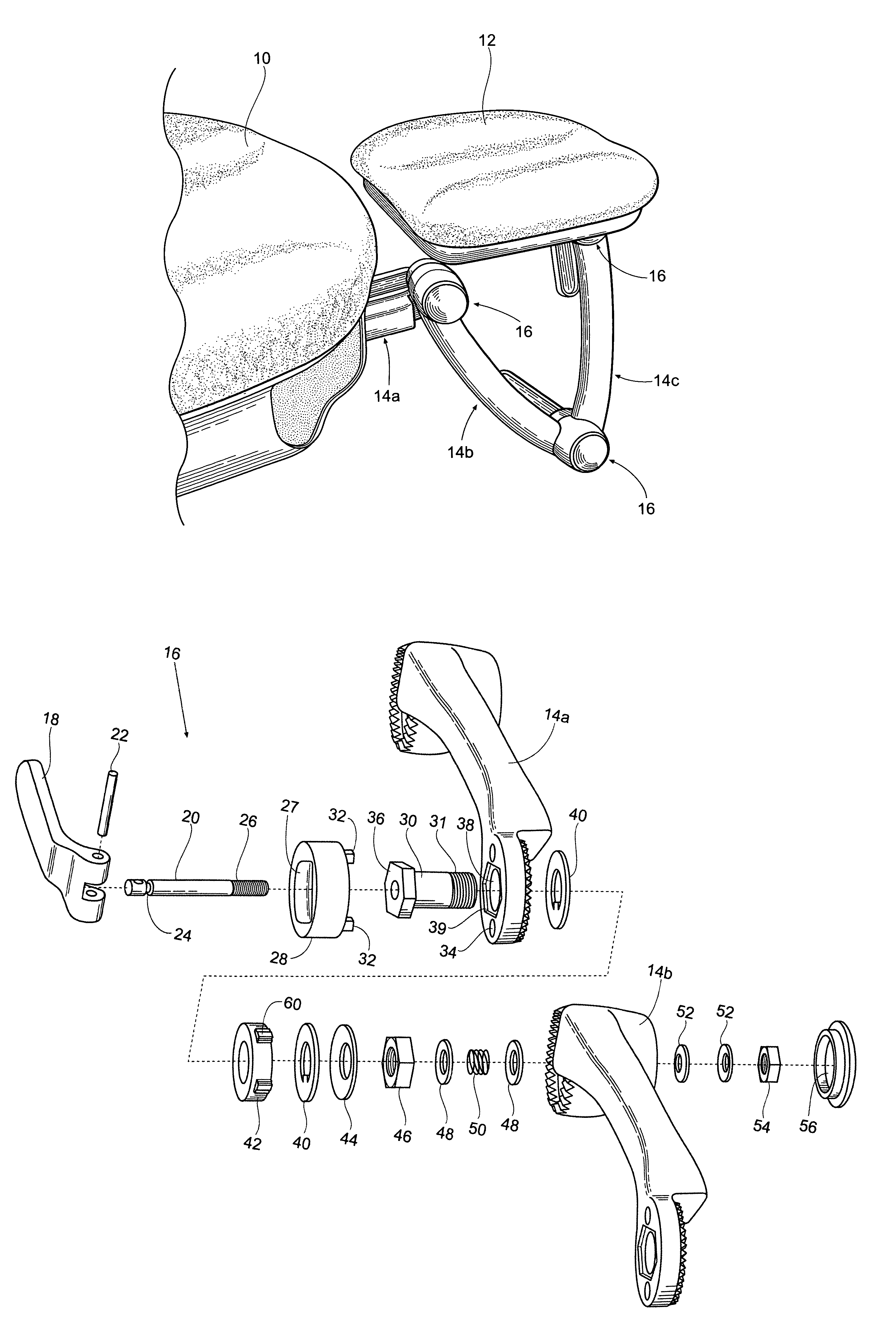
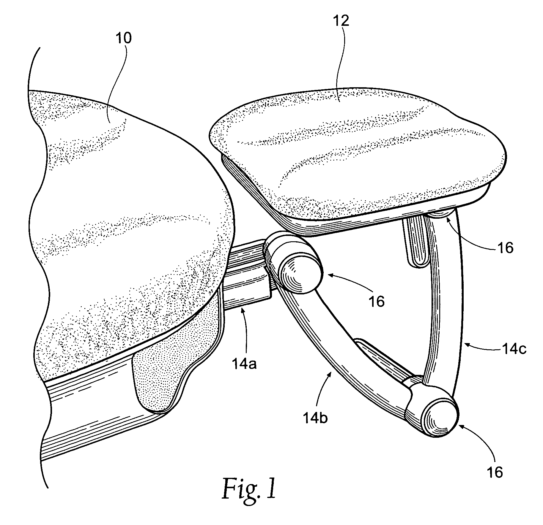
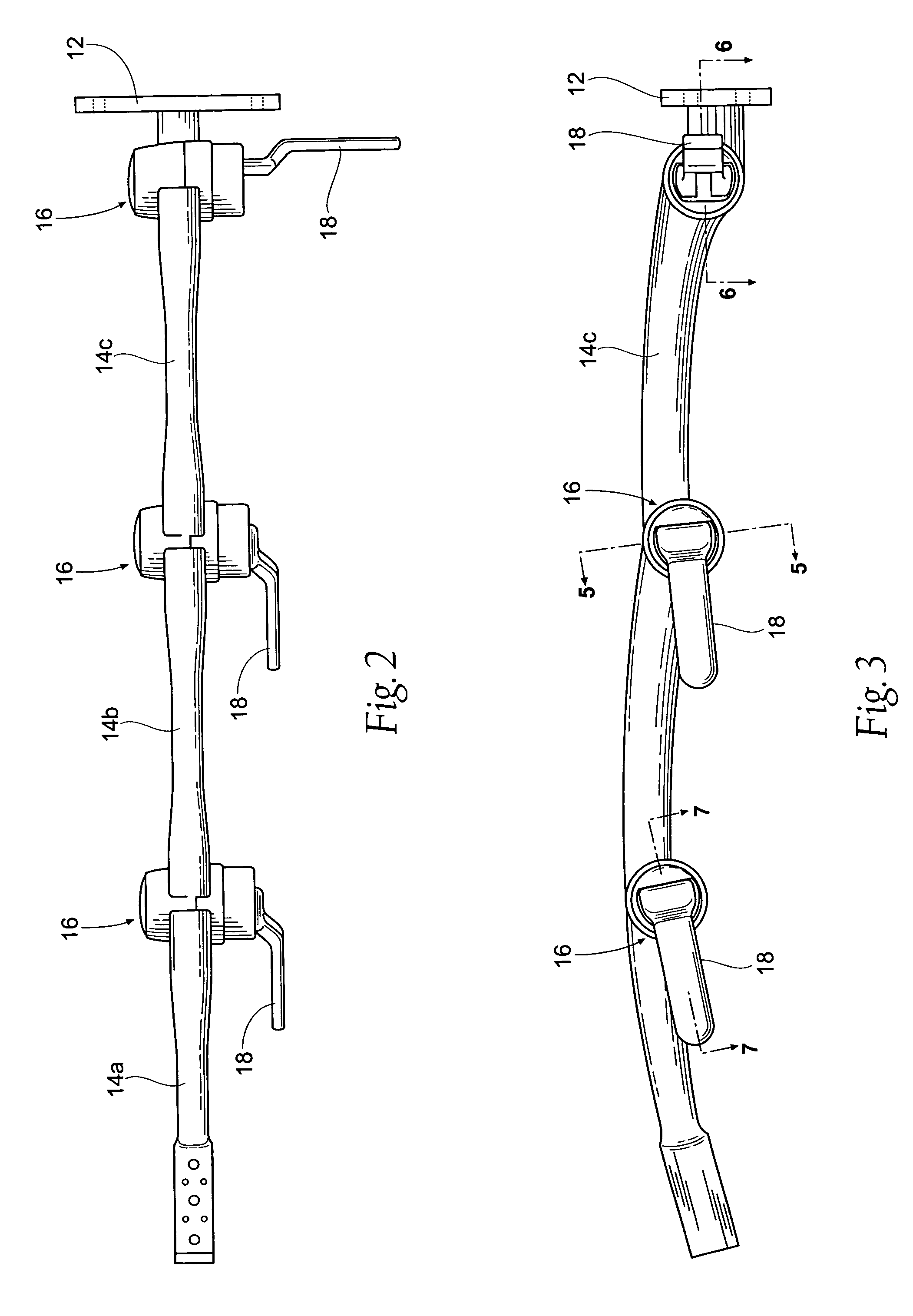
[0017]FIG. 1 shows a perspective sectional view of an examination table 10. The examination table 10 comprises a headrest 12, which is connected to the examination table 10 by a series of rotatably adjoined arms 14a, 14b, and 14c. The present invention comprises a linkage mechanism 16 that allows the arms 14a–14c to be rotatably connected to one another and also to the examination table 10 and the headrest 12. The linkage mechanisms 16 allow the headrest 12 to be secured in a wide array of angles and positions relative to the examination table 10. It should be noted that the arms 14a–14c may be ref...


PUM


Abstract

A linkage mechanism for an adjustable arm assembly. The linkage assembly may be used to support an object, such as a headrest for use in connection with an examination table. The linkage mechanism provides structure to interlock or disengage two adjoining arm sections. The linkage mechanism controls relative movement of two adjoining arm sections without affecting the movement of non-adjoined sections or the headrest. The linkage mechanism further provides friction retention means so that the adjoining arms will retain their relative position to one another even if they are not in an interlocked position.

Description

BACKGROUND OF THE INVENTION[0001]The present invention relates generally to adjustable medical equipment and, more specifically, to an adjustable head support and support arm for an adjustable table.[0002]During many examination procedures, the patient's head and neck may be repositioned if a different area of the neck or head is to be examined. If repositioning is necessary, the movement is preferably done with as little discomfort the patient as possible. Likewise, such repositioning should be performed easily by the medical examiner.[0003]Generally, a headrest is coupled to an extended arm that is mounted or attached to an examination table or chair. The arm typically has two or three adjustable sections, and the headrest may also be adjustable. Locking devices, such as screws, bolts, or plunger elements, have been utilized to hold the arm sections in place. However, such devices generally are cumbersome and do not afford the headrest any resistance when removed or released from ...

Claims


Application Information

Patent Timeline
Patent Type & Authority Patents(United States)
IPC IPC(8): A47C20/04A61G7/07A61G13/00A61G13/12A61G15/12
CPCA61G13/121A61G7/072A61G15/125A61G13/0018
Inventor DEBRAAL, JACK A.MARCHANT, MICHAEL J.
Owner BREWER COMPANY LLC THE
Why Eureka
Try Eureka