
Torque sensor for calibrating screwing tools

a torque sensor and screwing tool technology, applied in the field of torque sensors for calibrating screwing tools, can solve problems such as fixed installation, and achieve the effect of reducing the moment of inertia and low specific weigh

Active Publication Date: 2006-08-22
EDUARD WILLE GMBH & CO KG
View PDF5 Cites 12 Cited by
  • Summary
  • Abstract
  • Description
  • Claims
  • Application Information

AI Technical Summary

Benefits of technology

[0011]This can be achieved by different measures. One such measure consists of the inner body having radial dimensions which are small as compared to the radial dimensions of the annular body. Another measure is said inner body consisting of a material which has a low specific weight as compared with the material of the annular body. Eventually, said inner body may have regularly arranged apertures for reducing the moment of inertia.

Problems solved by technology

Thus the torque sensor does not measure the torque which is transmitted by a rotating shaft or the like, and, consequently, is not fixedly installed in the torque-transmitting assembly.

Method used


Image

  • Torque sensor for calibrating screwing tools
  • Torque sensor for calibrating screwing tools
  • Torque sensor for calibrating screwing tools

Examples


Embodiment Construction

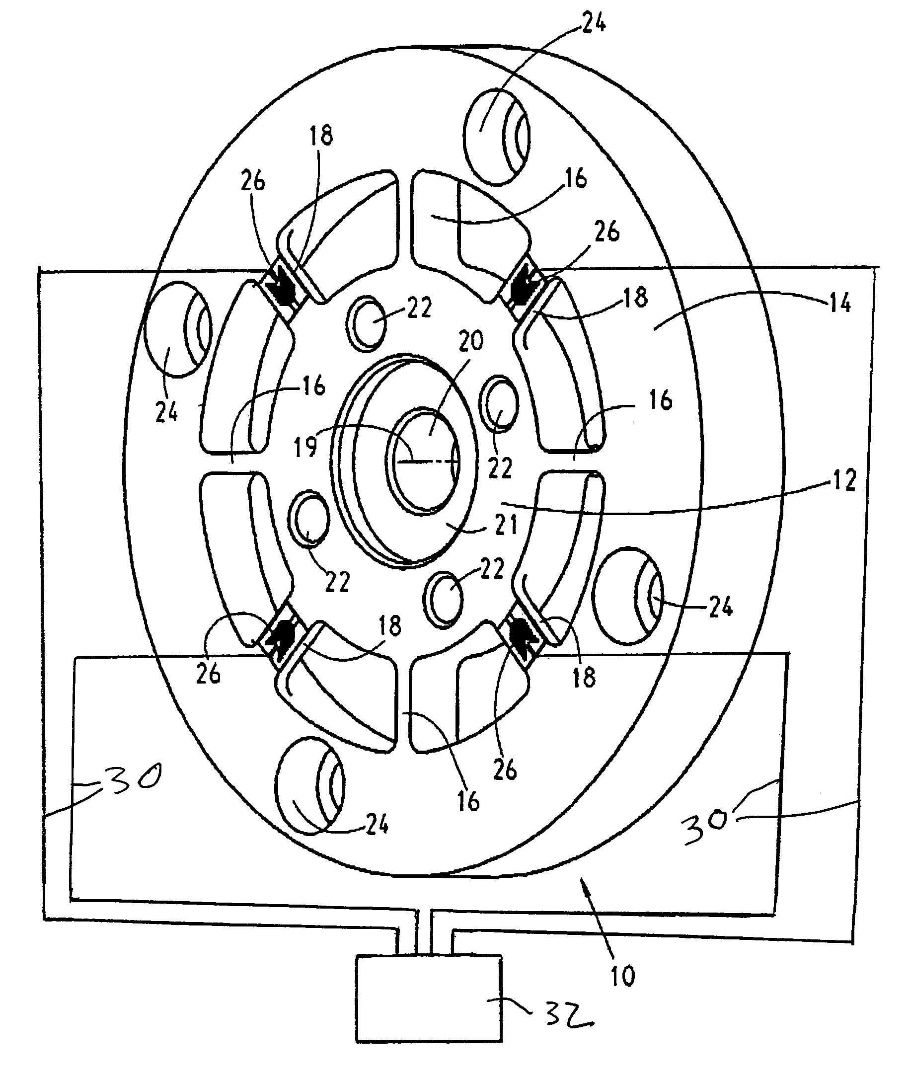
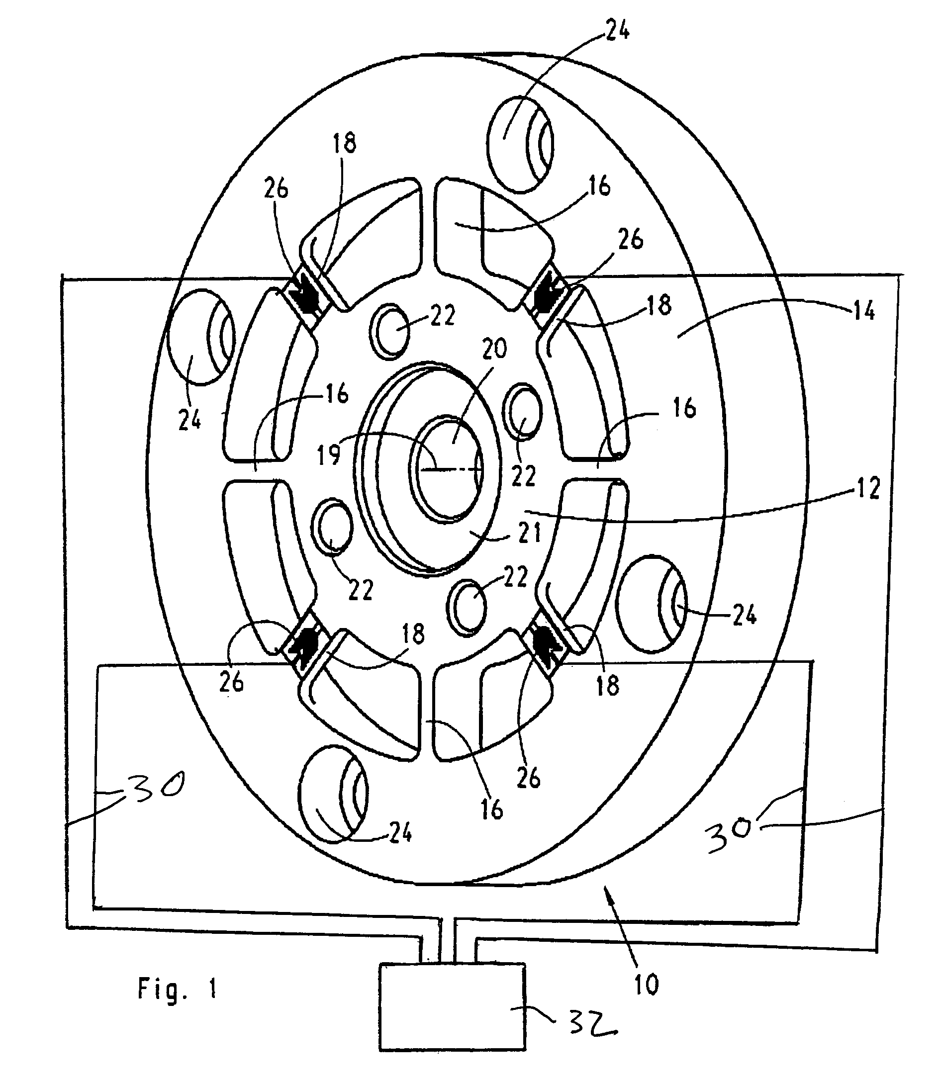
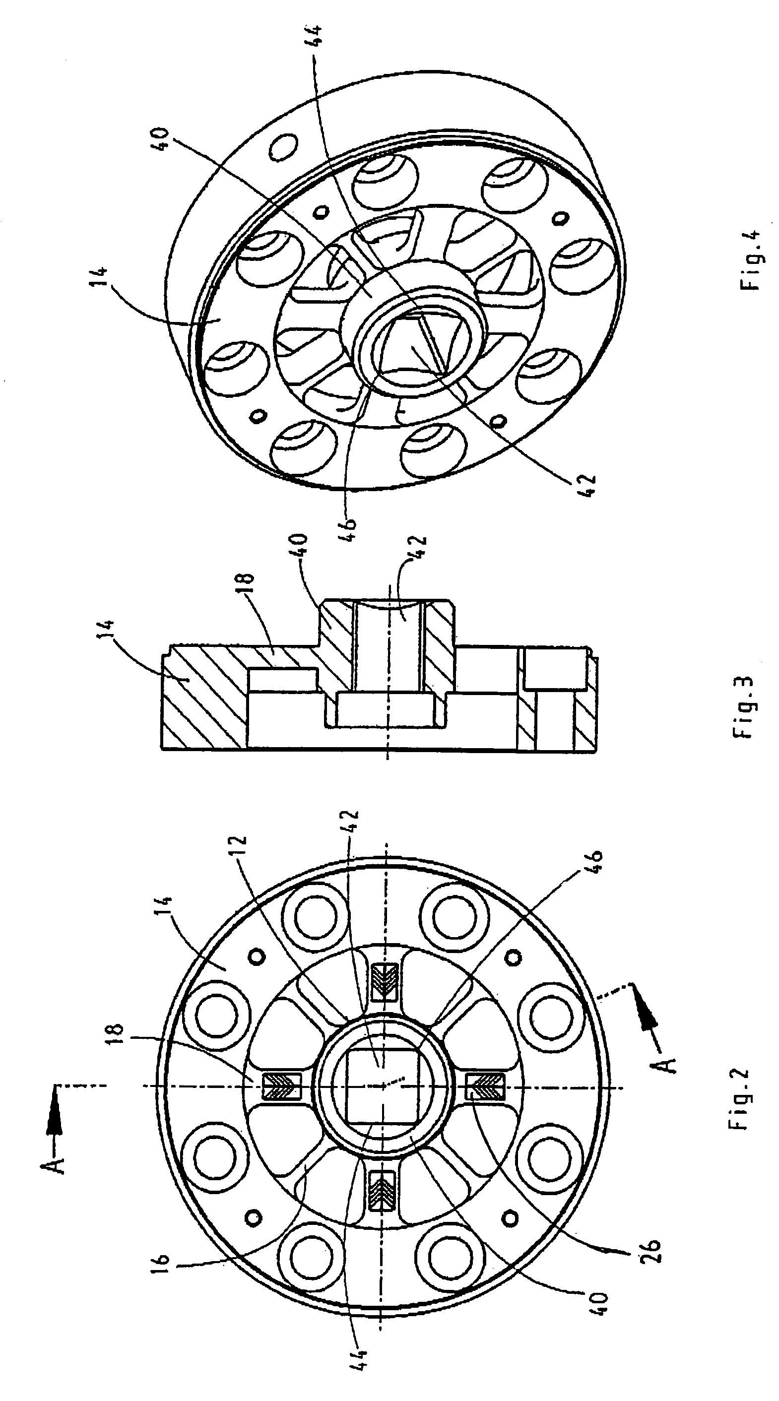
[0019]Referring to FIG. 1, numeral 10 generally designates a torque sensor. The torque sensor 10 has an inner body 12. The inner body 12 is surrounded coaxially by an outer annular body 14. The inner body 12 is connected with the outer annular body through webs 18 of a first type and webs 16 of a second type. The first type webs 18 are circumferentially wide as compared to the second type webs 16. The axial dimensions, however, of the first type webs are small. Virtually, the webs 18 are flat plates in a plane normal to the axis of the torque sensor. The second type webs 16 are narrow in circumferential direction. The axial dimensions of the webs 16, however, are large relative to the webs 18, the webs extending through the whole depth of the outer annular body 14.

[0020]The outer annular body is held stationary. To this end, the outer annular body is affixed to a carrier such as a wall by means of bolts (not shown) which pass through bores 24.

[0021]The webs 18 substantially take up ...


PUM

PropertyMeasurementUnit
torqueaaaaaaaaaa
widthaaaaaaaaaa
specific weightaaaaaaaaaa

Abstract

The invention relates to a torque sensor for calibrating screwing tools such as dynamometric keys or impact screw drivers. A torque sensor for calibrating screwing tools has an inner body defining an axis with respect to which a torque is to be measured. The inner body has a seat for engaugement of a screwing tool to be calibrated. An outer annular body is held stationary. This outer annular body is coaxial with the inner body and is connected therewith through radial webs of a first type and through radial webs of a second type. The first type webs have relatively large widths circumferentially but have relatively small axial dimensions. The second type webs are relatively narrow circumferentially but have relatively large axial dimensions. The torque sensor further comprises torsion measuring elements attached to said first type webs for measuring torsional deformation due to torques exerted on said inner body.

Description

BACKGROUND OF THE INVENTION[0001]The invention relates to a torque sensor for calibrating screwing tools such as dynamometric keys or impact screw drivers.[0002]DE 195 02 616 A1 discloses a torque sensor comprising an inner body having an axis with respect to which a torque is to be measured, and an outer annular body which surrounds the inner body coaxially and which is connected with the inner body through radial webs. There is a first type of web which has a relatively large width circumferentially but has relatively small axial dimensions. And there is a second type of web which is relatively narrow circumferentially but has relatively large axial dimensions. Measuring elements are attached to the first type webs.[0003]The prior art torque sensor serves for the measurement of a torque which is transmitted by rotating parts. The annular body is attached to one rotating part by bolts. The inner body is a ring which is attached to the other rotating body, also by means of axial bol...

Claims


Application Information

Patent Timeline
Patent Type & Authority Patents(United States)
IPC IPC(8): G01L3/00B25B23/14G01L3/10G01L3/14G01L25/00
CPCB25B23/14G01L25/003G01L3/1457
Inventor HERBOLD, SIEGFRIEDSCHWAFERTZ, RAINERWILHELM, JOACHIM
Owner EDUARD WILLE GMBH & CO KG
Learn More