Load application element and method to produce a load application element

Inactive Publication Date: 2018-05-10
MUBEA CARBO TECH
View PDF13 Cites 0 Cited by
  • Summary
  • Abstract
  • Description
  • Claims
  • Application Information

AI Technical Summary

Benefits of technology

The patent text discusses the use of aluminum for load introduction elements, as it has a high specific weight and can induce corrosion to carbon fiber reinforced plastics. The text describes methods to suppress electrochemical incompatibility, including extensive shielding and sealing of the materials. The second variation of the method involves inserting a reinforcing element made of composite layers into an outer housing and impregnating it with resin. The layers may be stitch-bonded or secured during resin injection to prevent misalignment. The technical effect of the patent text is to provide a solution for load introduction elements in composite structures that reduces the negative effects of aluminum and alleviates the issue of electrochemical corrosion.

Problems solved by technology

In the majority of applications force introduction into composite structures, such as made from fiber reinforced plastics, turns out to be challenging when compared to force introduction into structures made from more conventional materials.
One reason for this is that many composite materials are highly anisotropic, as well as relatively brittle when compared e.g. to conventional metal alloys.
Consequently, structures made from such materials may be highly sensitive to the way how forces are introduced into them.
For example drilling of holes and subsequent thread cutting in order to obtain force transmission points is in general not applicable because the structural weakening introduced by such measures is much higher in most composite structures than it is in conventional materials.

Method used


Image

  • Load application element and method to produce a load application element
  • Load application element and method to produce a load application element
  • Load application element and method to produce a load application element

Examples


Embodiment Construction

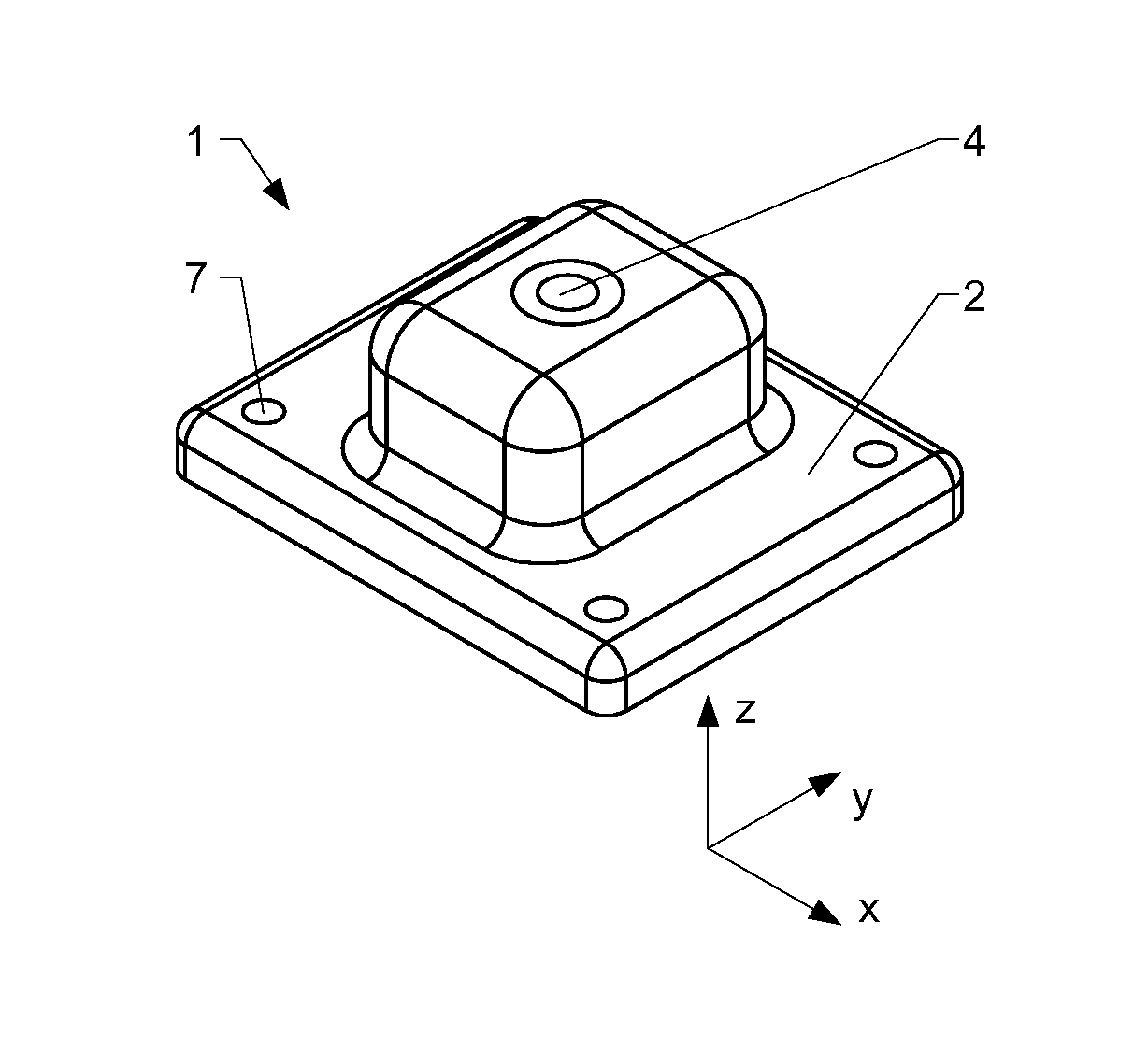
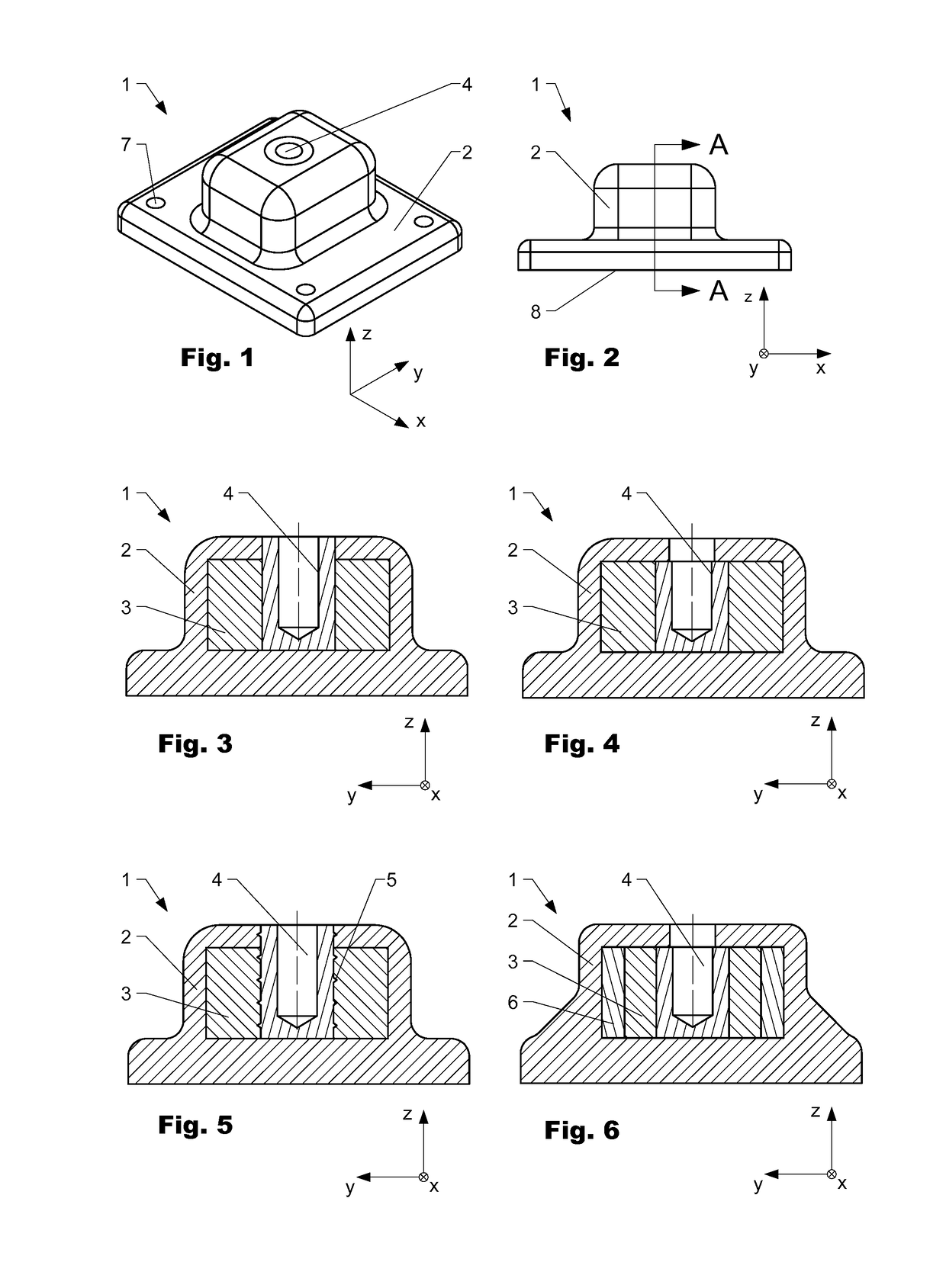
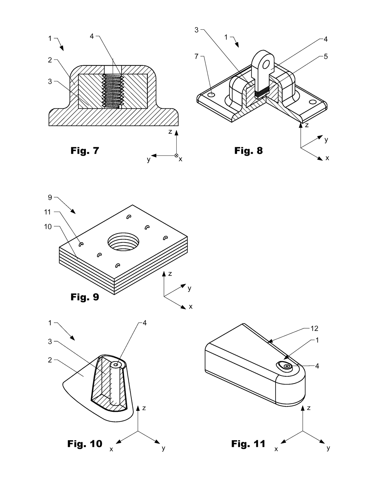
[0007]The load application elements known from the prior art have several drawbacks which, depending on the application, can turn out to be critical.

[0008]As for lightweight structures, which is an important field of application of composite structures, load application elements may contribute substantially to the total weight of a component part. This particularly holds true for load application elements made from metals, which still constitute the most widely used type of load application elements. As explained above, many composite structures are relatively sensitive to the way how they are loaded which often makes it necessary to distribute external forces that have to be applied to a composite structure over a larger area of the structure. In such applications the minimum spatial dimensions of a load application element may be mostly given by the loading case as well as the type of composite structure. Thus, the weight of a load application element may mainly depend on the spec...


PUM

PropertyMeasurementUnit
Shapeaaaaaaaaaa

Abstract

The invention is directed to a load application element (1) which comprises at least one reinforcing element (3) that comprises a layered setup from several layers of a composite material. The reinforcing element (3) is at least partially encompassed by an outer housing (2).

Description

[0001]The present invention is directed to a load application element and to a method to produce a load application element.BACKGROUND OF THE INVENTION[0002]In the majority of applications force introduction into composite structures, such as made from fiber reinforced plastics, turns out to be challenging when compared to force introduction into structures made from more conventional materials. One reason for this is that many composite materials are highly anisotropic, as well as relatively brittle when compared e.g. to conventional metal alloys. Consequently, structures made from such materials may be highly sensitive to the way how forces are introduced into them. For example drilling of holes and subsequent thread cutting in order to obtain force transmission points is in general not applicable because the structural weakening introduced by such measures is much higher in most composite structures than it is in conventional materials.[0003]Therefore a variety of specific device...

Claims


Application Information

Patent Timeline
IPC IPC(8): B29C70/74B29C45/14B29C70/22F16B37/04
CPCB29C70/745B29C45/14631B29C70/222F16B37/04
Inventor SCHMITZ, SEBASTIAN
Owner MUBEA CARBO TECH
Why Eureka
Try Eureka