Zoom lens and imaging apparatus

a zoom lens and imaging apparatus technology, applied in the field of zoom lenses, can solve the problems that the conventional lens cannot meet the demand, the image size to be imaged is not particularly large, etc., and achieve the effect of increasing the weight of the zoom lens, increasing the amount of lateral chromatic aberration, and high specific weigh

Active Publication Date: 2014-08-28
FUJIFILM CORP
View PDF3 Cites 3 Cited by
  • Summary
  • Abstract
  • Description
  • Claims
  • Application Information

AI Technical Summary

Benefits of technology

[0045]The advantageous effects described above will become more significant in the case that Conditional Formula (3)′ is satisfied within the range defined in Conditional Formula (3).
[0046]If the zoom lens of the present invention satisfies Conditional Formula (4), the following advantageous effects can be obtained. That is, Conditional Formula (4) defines the Abbe's numbers of the biconvex lens that constitutes the cemented lens within the 11 lens group. If the value of νd4 is less than the lower limit defined in Conditional Formula (4), the amount of lateral chromatic aberration will increase. If this lateral chromatic aberration is to be corrected by the other lens groups, the Abbe's numbers of the other lenses, for example, the Abbe's number of the second negative meniscus lens, will increase, which will result in glass materials having high specific weights being used, leading to an increase in the weight increase of the zoom lens. Inversely, if the value of νd4 is greater than the upper limit defined in Conditional Formula (4), the amount of lateral chromatic aberration will increase, and correction thereof will become difficult. The above shortcomings can be prevented if Conditional Formula (4) is satisfied, and weight reduction of the zoom lens can be realized while suppressing the amount of lateral chromatic aberration.
[0047]The advantageous effects described above will become more significant in the case that Conditional Formula (4)′ is satisfied, and further in the case that Conditional Formula (4)″ is satisfied within the range defined in Conditional Formula (4).
[0048]Particularly in the case that the 12 lens group has the basic configuration described above, variations in aberrations due to focusing operations can be suppressed. The advantageous effects of

Problems solved by technology

It cannot be said that the first lens group of these zoom lenses are sufficiently miniaturized, although image sizes to b

Method used


Image

  • Zoom lens and imaging apparatus
  • Zoom lens and imaging apparatus
  • Zoom lens and imaging apparatus

Examples


example 1

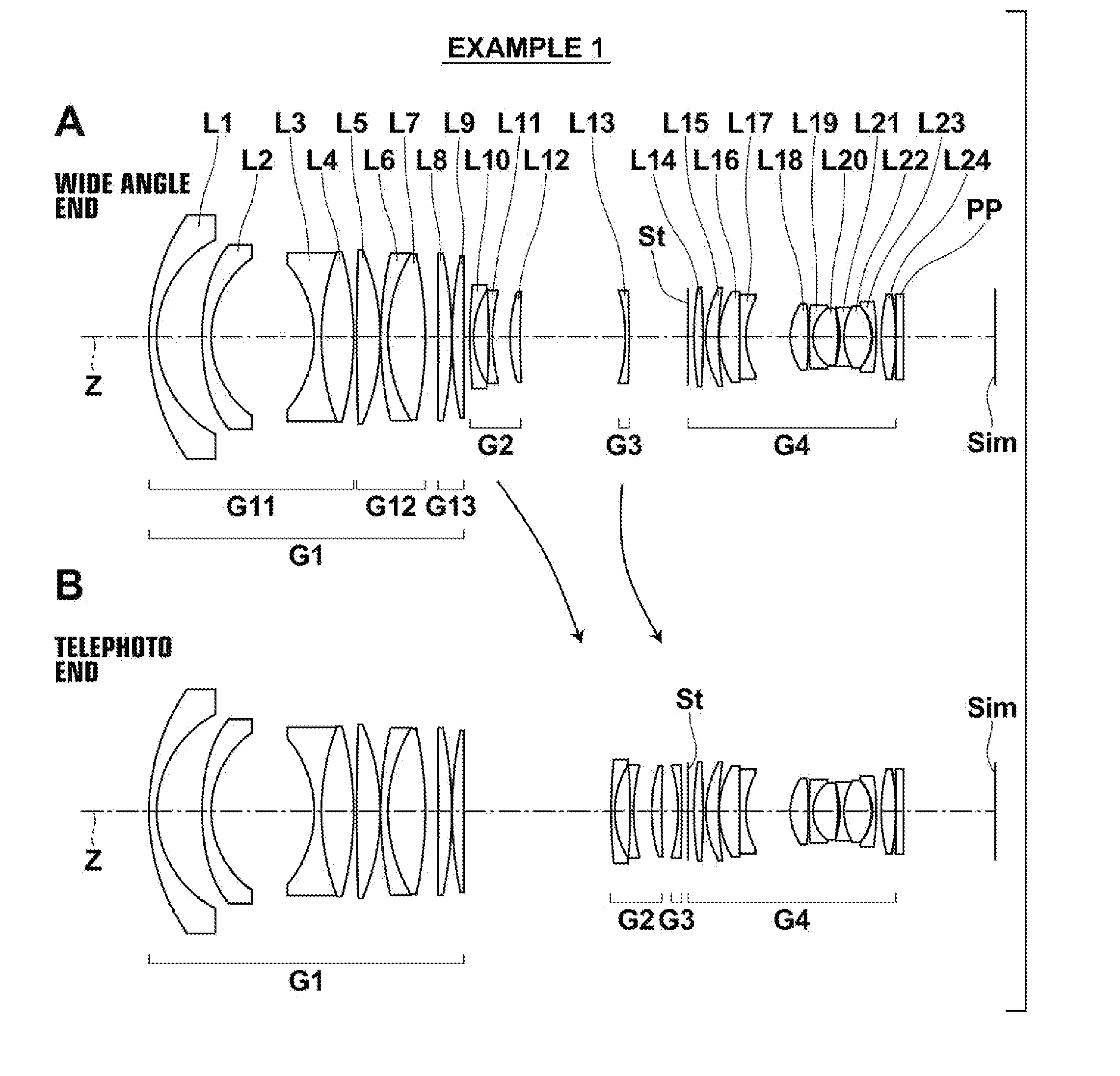
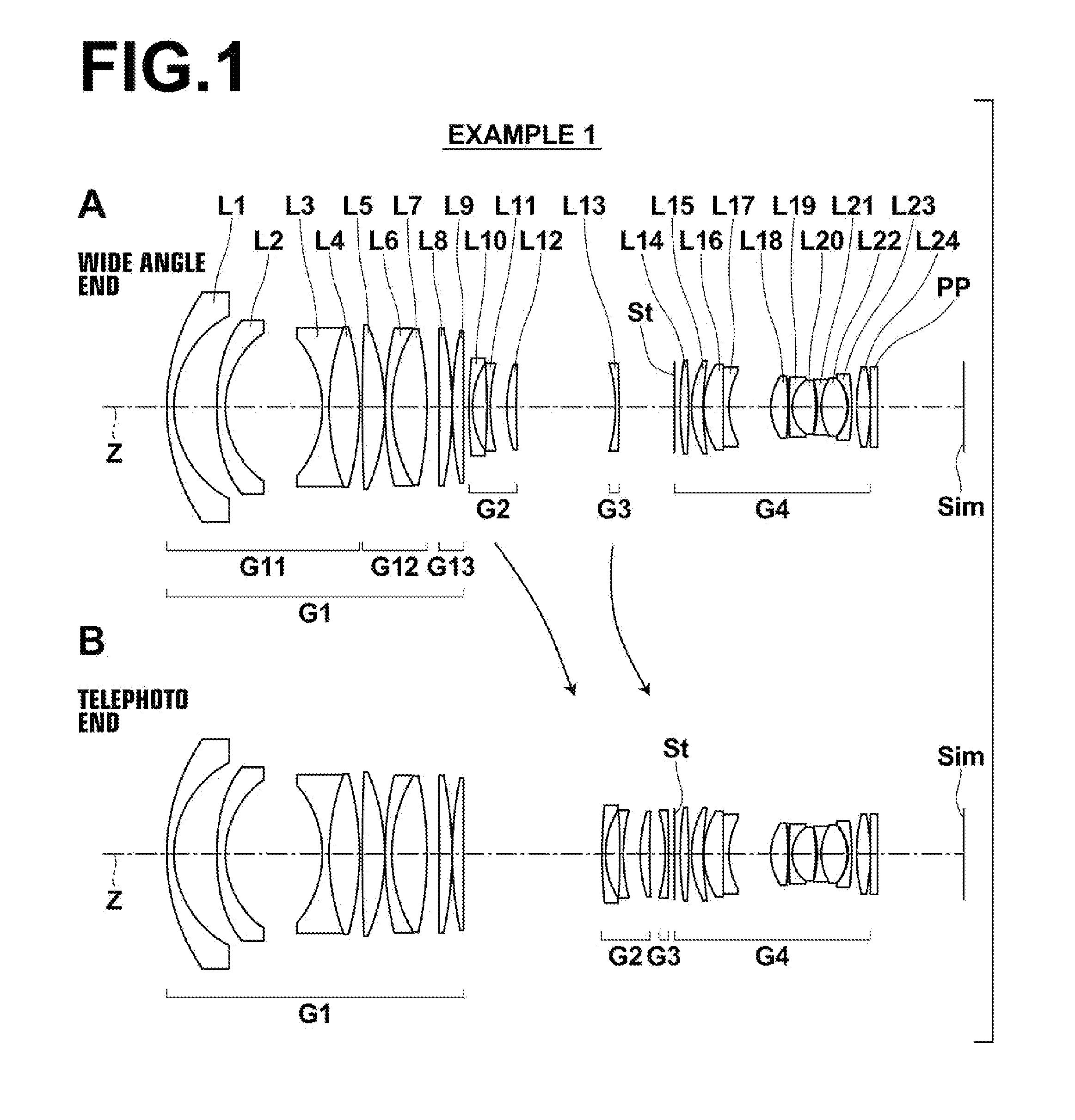
[0125]As described previously, the arrangements of the zoom lens of Example 1 at the wide angle end and at the telephoto end are illustrated in FIG. 1. Note that detailed descriptions of the lens groups and each lens in the configuration of FIG. 1 have already been given, and therefore redundant descriptions will be omitted below unless particularly necessary.

[0126]Table 1 shows basic lens data of the zoom lens of Example 1. Table 1 also shows data regarding the optical member PP. In Table 1, ith (i=1, 2, 3, . . . ) lens surface numbers that sequentially increase from the object side to the image side, with the lens surface at the most object side designated as first, are shown in the column Si. The radii of curvature of ith surfaces are shown in the column Ri, and the distances between an ith surface and an i+1st surface along the optical axis Z are shown in the column Di. The refractive indices of jth (j=1, 2, 3, . . . ) optical elements from the object side to the image side with...

example 2

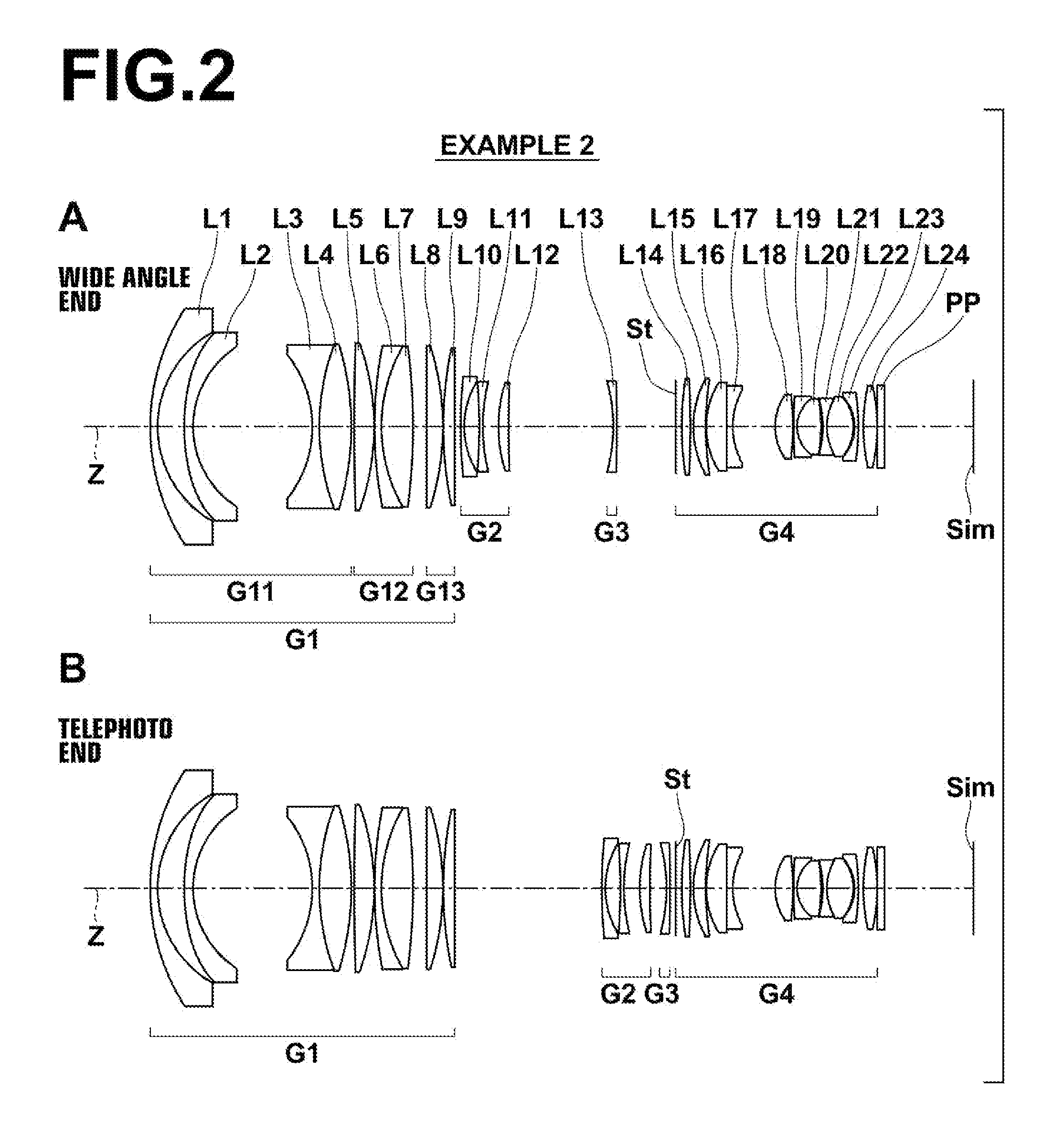
[0140]FIG. 2 illustrates the arrangements of lens groups of a zoom lens according to Example 2 at the wide angle end and at the telephoto end. The zoom lens of Example 2 has approximately the same configuration as that of the zoom lens according to Example 1 described above. However, the zoom lens of Example 2 differs from the zoom lens of Example 1 in four points, that an eighth lens L8 of a 13 lens group G13 is a planoconvex lens having a convex surface toward the image side, that a ninth lens L9 of the 13 lens group G13 is a planoconvex lens having a convex surface toward the object side, that a sixteenth lens L16 of a fourth lens group G4 is a planoconvex lens having a convex surface toward the object side, and that a seventeenth lens L17 of the fourth lens group G4 is a planoconcave lens having a concave surface toward the image side.

[0141]Note that the zoom lenses of Example 2 through 9 differ from the zoom lens of Example 1 in the same four points. Therefore, the above descri...

example 3

[0143]FIG. 3 illustrates the arrangements of lens groups of a zoom lens according to Example 3 at the wide angle end and at the telephoto end.

[0144]Table 7 shows basic lens data of the zoom lens of Example 3. Table 8 shows data related to zoom of the zoom lens of Example 3. Table 9 shows aspherical surface data of the zoom lens of Example 3. A through H of FIG. 13 are diagrams that illustrate various aberrations of the zoom lens of Example 3.

TABLE 7Example 3: Basic Lens DataSiRindjνdj(Surface(Radius ofDi(Refractive(Abbe'sNumber)Curvature)(Distance)Index)Number)172.22772.5001.7725049.60236.085614.893*380.49403.0001.7173629.52432.605234.0445−37.47142.3511.5174252.43675.677012.5861.6585857.457−72.73861.0008773.96936.1641.4970081.549−98.13990.15310123.01222.3501.8830040.761155.001010.3981.4970081.5412−275.35064.96713∞5.5511.4970081.5414−89.86650.15015139.98963.8451.7085655.7316∞VariableDistance 1617162.70641.2001.7395353.711829.30095.20519−228.94471.2001.5737856.132064.05825.0552147.815...


PUM


Abstract

A zoom lens includes first, second, third, and fourth lens groups respectively having positive, negative, negative, and positive powers. The first lens group includes an 11 lens group having a negative power, which is fixed during focusing operations, a lens group having a positive power, which moves during focusing operations, and a lens group having a positive power, which is fixed during focusing operations. The 11 lens group includes two negative meniscus lenses having concave surfaces toward an image side, and a cemented lens constituted by a biconcave lens toward an object side and a biconvex lens toward the image side. A distance D4 between the second meniscus lens and the cemented lens and the focal distance f1 of the first lens group satisfy the relationship: 0.60<D4/f1<2.0. Thereby, variations in angles of view while changing magnification are suppressed, sufficient reductions in size and weight, and high performance are achieved.

Description

TECHNICAL FIELD[0001]The present invention is related to a zoom lens. Particularly, the present invention is related to a zoom lens which can be favorably employed in imaging apparatuses such as electronic cameras.[0002]In addition, the present invention is related to an imaging apparatus equipped with such a zoom lens.RELATED ART[0003]Zoom lenses are often mounted on imaging apparatuses, such as digital cameras, digital cinema cameras, video cameras, broadcast cameras, and surveillance cameras. Among such imaging apparatuses, there is particular demand for broadcast cameras and digital cinema cameras to have wide angles of view and to suppress variations in angles of view during focusing operations. Various zoom lenses have been conventionally proposed in order to meet this demand.[0004]For example, Japanese Unexamined Patent Publication Nos. 6 (1994)-242378, 9 (1997)-015501, 10 (1998)-062686, and Japanese Patent Publication No. 59 (1984)-004686 disclose zoom lenses in which a firs...

Claims


Application Information

Patent Timeline
IPC IPC(8): G02B15/177G02B13/00
CPCG02B15/177G02B13/009G02B15/144109
Inventor TOYAMA, NOBUAKICHO, MICHIO
Owner FUJIFILM CORP
Why Eureka
Try Eureka