Method and system for rapid and controlled elevation of a raisable floor for pools

Active Publication Date: 2011-09-01
BROCK DOVI
View PDF10 Cites 3 Cited by
  • Summary
  • Abstract
  • Description
  • Claims
  • Application Information

AI Technical Summary

Benefits of technology

[0015]According to the disclosed technique there is provided a novel system and method for rapidly elevating a sunken platform from the pool bottom pool floor, which overcomes the disadvantages of the prior art.
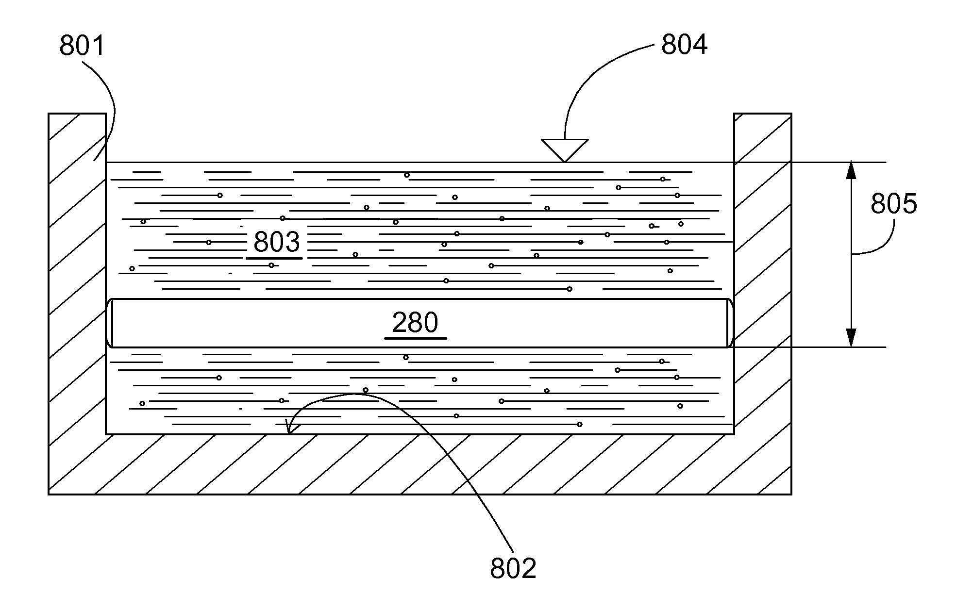
[0048]According to still another feature of the present invention, the stage of elevating a raisable floor to a water surface in the pool includes the sub-stages of: (i) keeping a predetermined amount of flotation fluid inside ballasting receptacle inner volumes of the raisable floor for controlling a raisable floor specific gravity, wherein the raisable floor is laying on a pool bottom; (ii) infusing flotation fluid inside the ballasting receptacle inner volumes of the raisable floor for controlled elevation of the raisable floor; (iii) measuring modular floor elements depth difference inside the water among certain of the at least two modular floor elements; (iv) balancing the raisable floor by infusing controlled amount of flotation fluid into the ballasting receptacle inner volumes; and (v) limiting a movement of air within the ballasting receptacle inner volume according to modular floor elements depths, for the purpose of improving a stability of the raisable floor and its controllability.

Problems solved by technology

The background art does not teach or suggest a system for rescue of a drowning victim from the water which works automatically, at sufficient speed and reliability.

Method used


Image

  • Method and system for rapid and controlled elevation of a raisable floor for pools
  • Method and system for rapid and controlled elevation of a raisable floor for pools
  • Method and system for rapid and controlled elevation of a raisable floor for pools

Examples


Embodiment Construction

[0076]The present invention includes a method and system for rapid and controlled elevation of a raisable floor for pools. The principles and operation of a rapid elevation floor system according to the present invention may be better understood with reference to the drawings and the accompanying description.

[0077]Before explaining at least one embodiment of the invention in detail, it is to be understood that the invention is not limited in its application to the details of construction and the arrangement of the components set forth in the following description or illustrated in the drawings.

[0078]Unless otherwise defined, all technical and scientific terms used herein have the same meaning as commonly understood by one of ordinary skill in the art to which this invention belongs. The materials, dimensions, methods, and examples provided herein are illustrative only and are not intended to be limiting.

[0079]It will be noted that the manner in which the elements of the present inve...


PUM

PropertyMeasurementUnit
Timeaaaaaaaaaa
Densityaaaaaaaaaa
Weightaaaaaaaaaa

Abstract

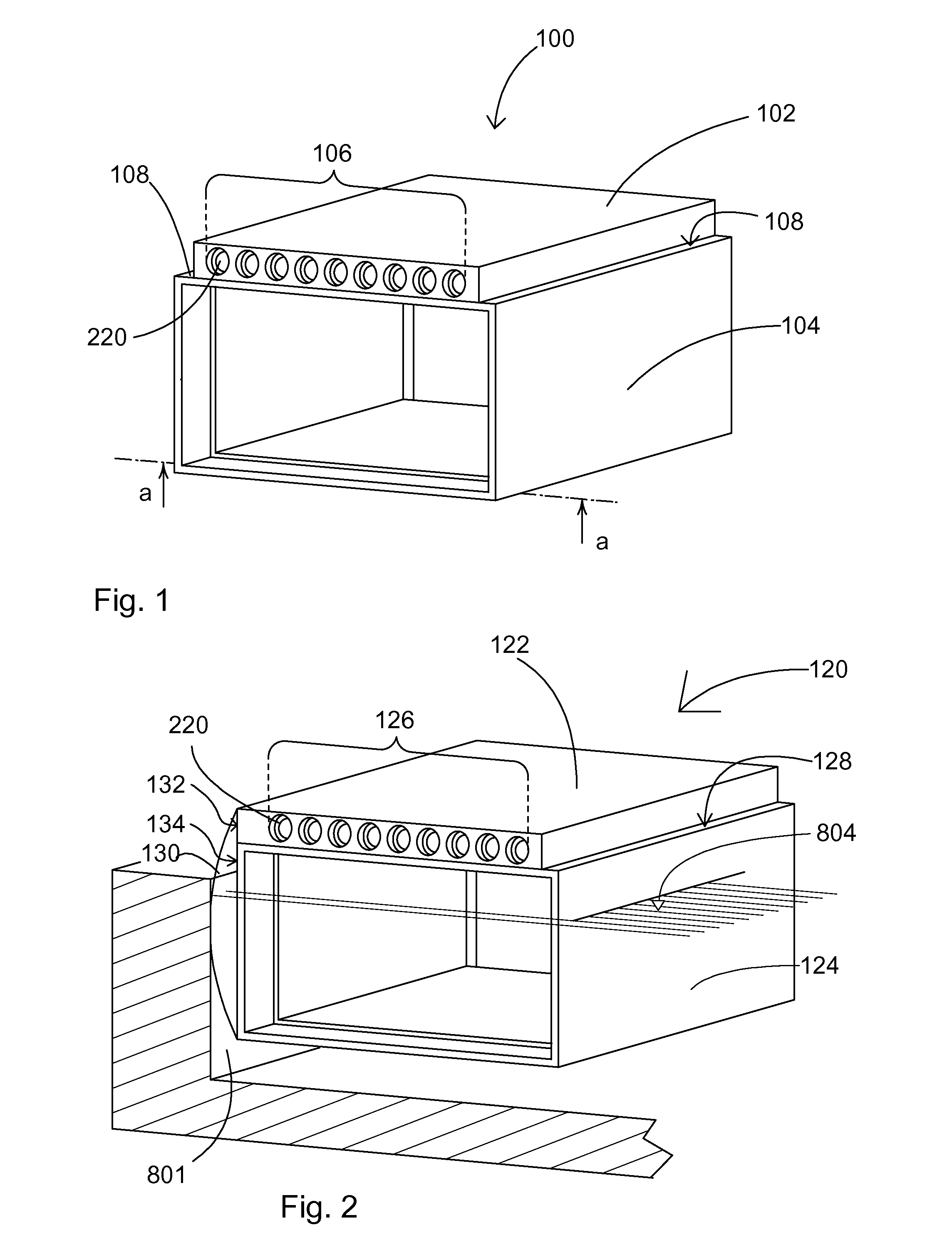
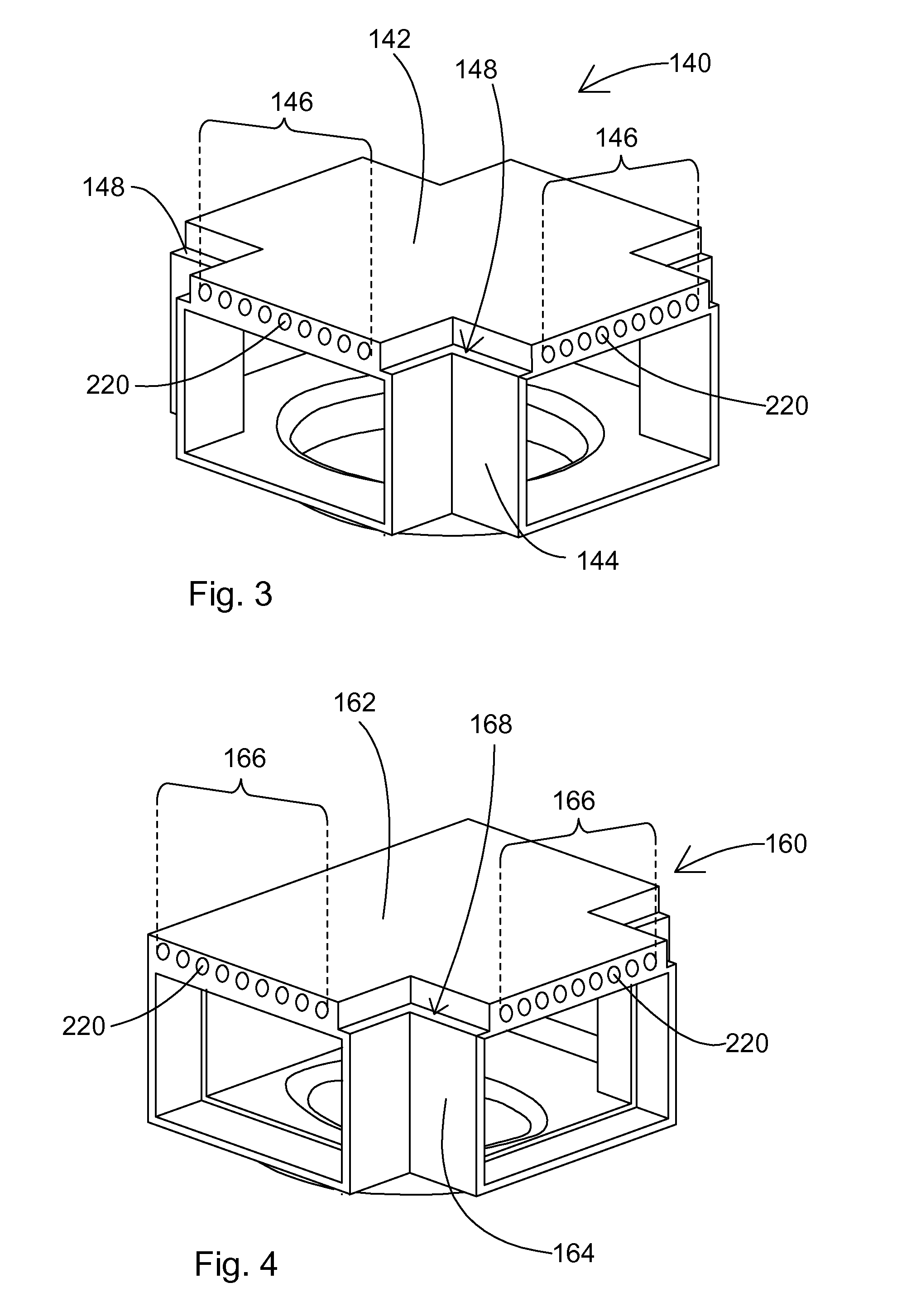
A rapid elevation floor system for a pool at least partially filled with pool water, including a raisable floor for disposing over the bottom of the pool. The raisable floor is combined of a plurality of modular floor elements, at least some of which include a ballasting receptacle. The ballasting receptacle is adapted to receive and discharge a volume of a flotation fluid lighter than the pool water, enabling the pool water to occupy any part of the volume when unoccupied by the flotation fluid. When the raisable floor is disposed beneath the surface of the pool water, the amount of the flotation fluid contained in the raisable floor is adjusted to render the specific weight of the raisable floor as equal to, or as slightly greater than the specific weight of the pool water, such that pumping of the flotation fluid into the ballasting receptacle(s) urges a rapid elevation of the raisable floor.

Description

CROSS-REFERENCE TO RELATED APPLICATIONS[0001]This application is a continuation-in-part application of International Application No. PCT / IL2009 / 001081, filed on Nov. 17, 2009, which claims priority of U.S. Provisional Patent Application No. 61 / 115,222, filed on Nov. 17, 2008, both of which are incorporated in their entirety herein by reference.FIELD OF THE INVENTION[0002]The present invention relates to a raisable floor for pools and more particularly, to a method and a system for rapid and controlled elevation of a raisable floor for pools.BACKGROUND OF THE INVENTION[0003]Raisable pool floors for aquatic pools are known in the art. In standard practice, the buoyancy of the raisable pool floors is adjusted by pumping air into a ballasting receptacle, to change the pool floor depth.[0004]U.S. Pat. No. 6,253,390 of Laks, entitled “Aquatic Raisable Floor Apparatus”, which is incorporated by reference for all purposes as if fully set forth herein, is directed to a pool floor system, whi...

Claims


Application Information

Patent Timeline
IPC IPC(8): E04H4/14B23P17/04
CPCY10T29/49826E04H4/065H01L31/022433H01L31/068H01L31/1804Y02E10/547Y10T29/49002Y02P70/50H01L31/18E04H4/00
Inventor BROCK, DOVI
Owner BROCK DOVI
Why Eureka
Try Eureka