Coatings for aircraft fuselage surfaces to produce electricity for mission-critical systems on military aircraft

a technology for aircraft fuselage surfaces and mission-critical systems, which is applied in the direction of sustainable manufacturing/processing, paper/cardboard containers, and final product manufacturing, etc. it can solve the problems of reducing fuel efficiency and making little sense of traditional inorganic pv for aircraft applications, and achieves low specific weight, reduce fuel efficiency, and increase wind resistance

Inactive Publication Date: 2015-03-26
SOLARWINDOW TECH
View PDF10 Cites 0 Cited by
  • Summary
  • Abstract
  • Description
  • Claims
  • Application Information

AI Technical Summary

Benefits of technology

[0004]The present invention recognizes that one way to add functionality to aircraft surfaces is by covering them in photovoltaics (PV), which can provide electricity to help power mission-critical systems on-board the aircraft. Traditional inorganic PV makes little sense for aircraft applications for a number of reasons, however, including excessive weight and potentially bulky structures that could increase wind resistance, both of which would reduce fuel efficiency. Organic PV (OPV) has a number of features that makes it potentially attractive for application in military aircraft, including low specific weight (W / g), flexibility, and thickness of the thin films. An important feature is the very low specific weight of OPV, as compared to other PV technologies, which could minimize any impact on fuel efficiency. Additionally, OPV is inherently flexible, which potentially allows unique application methods for non-planar surfaces, such as curved fuselage surfaces. Furthermore, the tunable nature of the absorption in OPV materials allows customized power production and surface appearances, which can be important for specialized military aircraft.
[0006]These problems and others are addressed by the present invention, a first exemplary embodiment of which comprises an OPV device, comprising one or more cells connected in series and / or parallel, applied as a film to conventional military aircraft surfaces. In this embodiment, the OPV coating is applied as a completed device onto the aircraft surface using a thin, flexible substrate with pressure-sensitive adhesives, which is described in detail in Applicants' related applications. In such a fashion, the OPV device can be fabricated in a high-throughput manner via roll-to-roll manufacturing onto a flexible planar substrate (with backing material, if necessary) that is then applied to both planar and curved aircraft surfaces. The OPV device can then be wired into the electrical systems via small connection terminals in, or below, the aircraft surface, and any necessary power electronics, such as inverters, batteries, and the like can be located inside the aircraft. The top surface of the OPV device-coated aircraft is then via a protective hard clear-coat (e.g. a clear epoxy coating), to protect the OPV device from physical damage and environmental stress, and from moisture and oxygen ingress, ensuring a superior lifetime. In such a way, the surfaces of the aircraft can be turned into electricity-generating surfaces to help power mission-critical systems, while adding minimal weight, and resulting in a smooth, hard, low-drag surface, to minimize any loss of fuel efficiency. Furthermore, by selecting appropriate OPV material absorption properties, the surface visual effect can be matched to the aircraft design profile, while still generating power.

Problems solved by technology

Traditional inorganic PV makes little sense for aircraft applications for a number of reasons, however, including excessive weight and potentially bulky structures that could increase wind resistance, both of which would reduce fuel efficiency.

Method used


Image

  • Coatings for aircraft fuselage surfaces to produce electricity for mission-critical systems on military aircraft
  • Coatings for aircraft fuselage surfaces to produce electricity for mission-critical systems on military aircraft
  • Coatings for aircraft fuselage surfaces to produce electricity for mission-critical systems on military aircraft

Examples


Embodiment Construction

[0015]The present invention now is described more fully hereinafter with reference to the accompanying drawings, in which embodiments of the invention are shown. This invention may, however, be embodied in many different forms and should not be construed as limited to the embodiments set forth herein; rather, these embodiments are provided so that this disclosure will be thorough and complete, and will fully convey the scope of the invention to those skilled in the art.

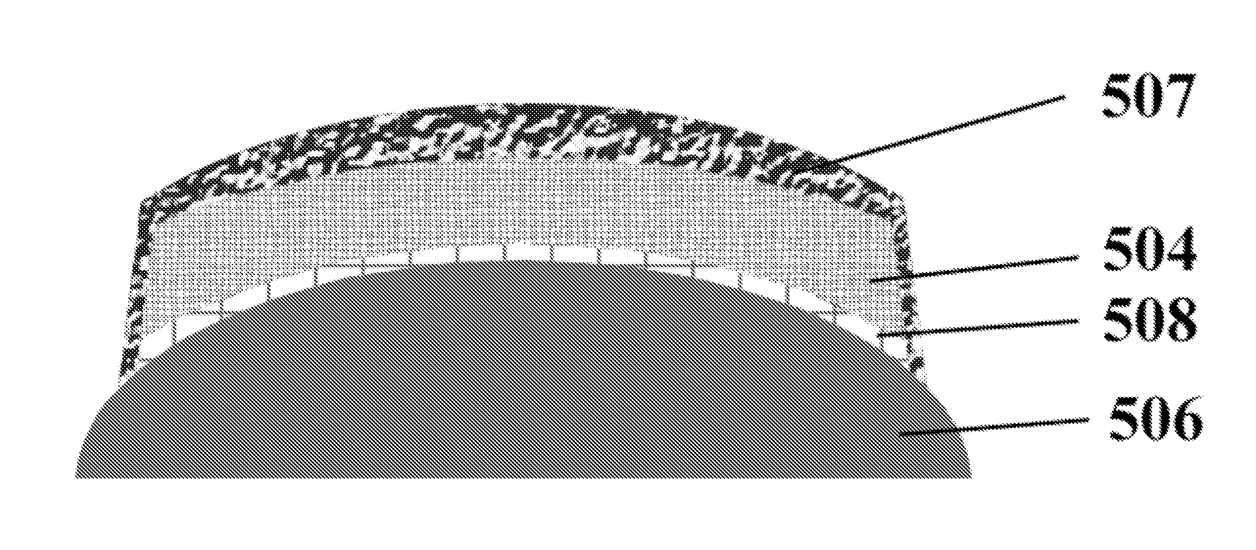
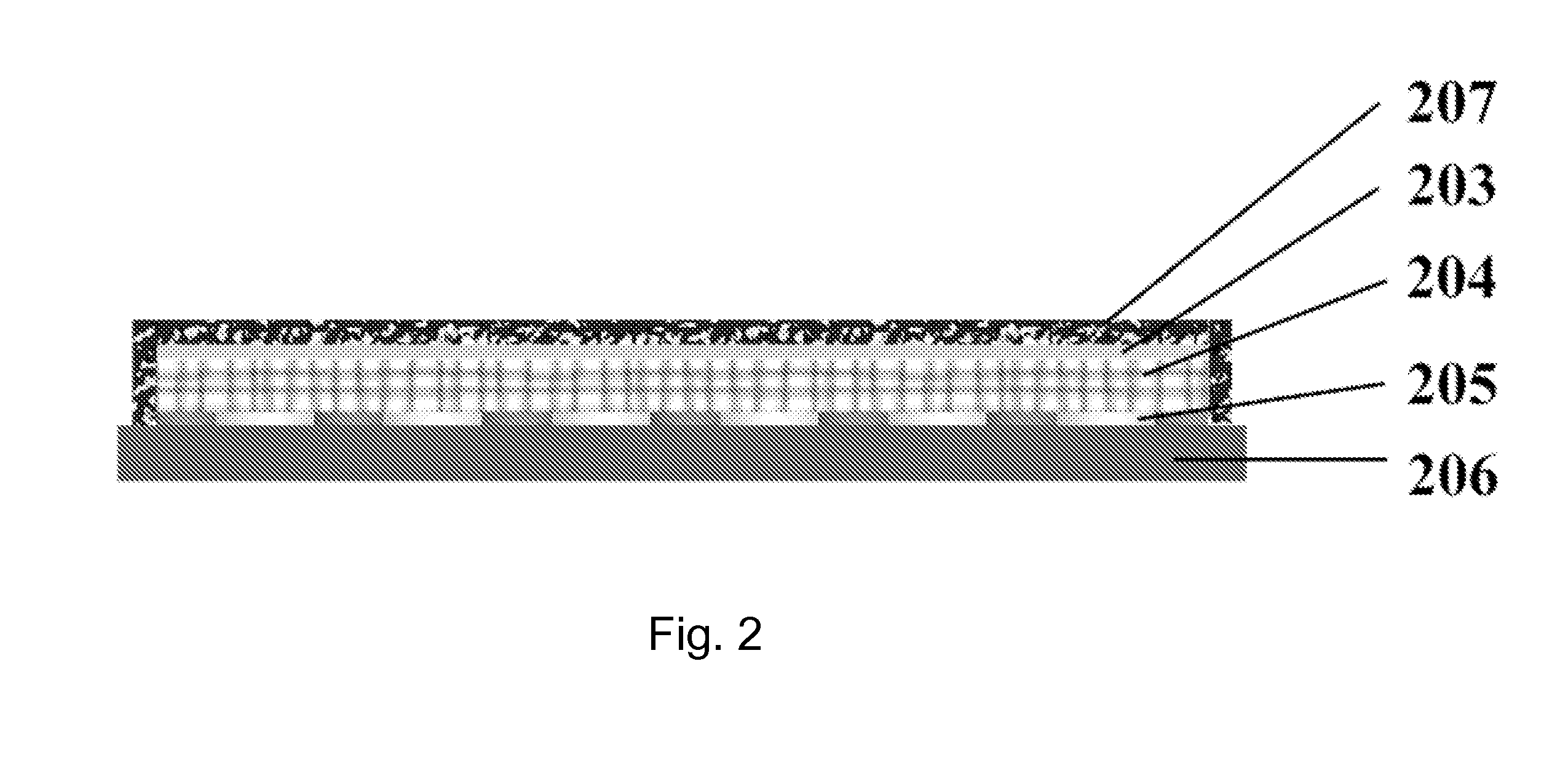
[0016]Referring now to the drawings, FIGS. 1-5 illustrate exemplary embodiments of electricity-generating coatings for military aircraft fuselage surfaces (FIGS. 4-5) and their manufacture (FIG. 1).

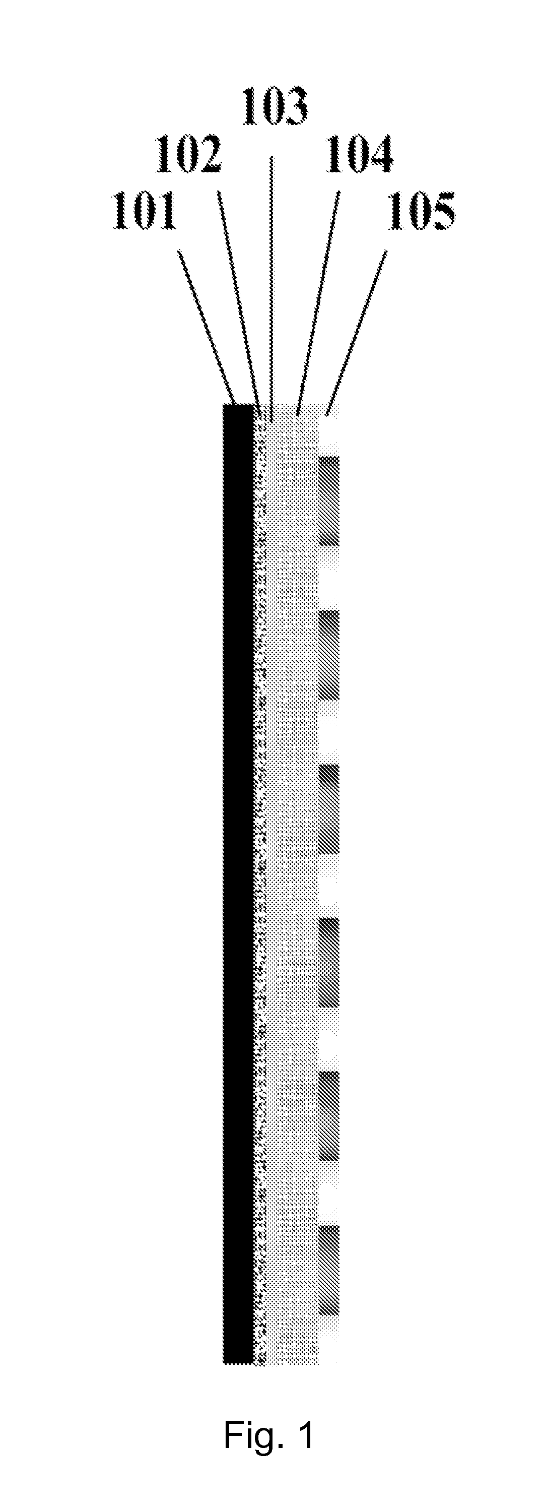
[0017]Referring to FIG. 1, which provides a cross-sectional view of an intermediate film stack produced for the eventual fabrication of electricity-generating coatings for military aircraft fuselage surfaces, the film is prepared upon a temporary base layer 101, in order to provide sufficient rigidity to allow conventional ...


PUM

PropertyMeasurementUnit
pressure-aaaaaaaaaa
flexible transparentaaaaaaaaaa
thickaaaaaaaaaa

Abstract

A variety of methods for fabricating organic photovoltaic-based electricity-generating military aircraft fuselage surfaces are described. In particular, a method for fabricating curved electricity-generating military aircraft fuselage surfaces utilizing lamination of highly flexible organic photovoltaic films is described. High-throughput and low-cost fabrication options also allow for economical production.

Description

CROSS-REFERENCE TO RELATED APPLICATIONS[0001]This application claims priority under 35 U.S.C. 119(e) of U.S. Provisional Application No. 61 / 841,243, filed on Jun. 28, 2013 (Attorney Docket No. 7006 / 0141PR01), U.S. Provisional Application No. 61 / 842,355, filed on Jul. 2, 2013 (Attorney Docket No. 7006 / 0141PR02), U.S. Provisional Application No. 61 / 841,244, filed on Jun. 28, 2013 (Attorney Docket No. 7006 / 0142PR01), U.S. Provisional Application No. 61 / 842,357, filed on Jul. 2, 2013 (Attorney Docket No. 7006 / 0142PR02), U.S. Provisional Application No. 61 / 841,247, filed on Jun. 28, 2013 (Attorney Docket No. 7006 / 0143PR01), U.S. Provisional Application No. 61 / 842,365, filed on Jul. 2, 2013 (Attorney Docket No. 7006 / 0143PR02), U.S. Provisional Application No. 61 / 841,248, filed on Jun. 28, 2013 (Attorney Docket No. 7006 / 0144PR01), U.S. Provisional Application No. 61 / 842,372, filed on Jul. 2, 2013 (Attorney Docket No. 7006 / 0144PR02), U.S. Provisional Application No. 61 / 842,796, filed on Jul...

Claims


Application Information

Patent Timeline
Patent Type & Authority Applications(United States)
IPC IPC(8): H02S10/40B32B37/12H01L51/44B32B37/00H02S30/20H01L51/00B32B37/24B32B38/10
CPCH02S10/40B32B37/24B32B37/12B32B38/10B32B2605/18H02S30/20H01L51/0097H01L51/448B32B2037/243B32B37/025B29L2031/3076B29L2031/778B29C63/0073B29C63/02B29C63/0013Y10T156/10B32B37/003B32B38/0012B32B38/1866B32B2037/268B32B2038/0028B32B2307/412B32B2367/00B32B2457/12B32B2313/04B32B2323/04Y02E10/549Y02P70/50H10K77/111H10K30/88H01L31/0481H10K30/30H10K30/83H10K71/18H10K71/80H10K77/10H01L31/0468B32B37/26B32B2307/20B32B2605/006B32B2307/202B32B2311/08B32B2386/00H02S40/30
Inventor CONKLIN, JOHN ANTHONYHAMMOND, SCOTT RYAN
Owner SOLARWINDOW TECH
Why Eureka
Try Eureka