
Fragrance dispenser, domestic appliance including such a fragrance dispenser, and cartridge for such a fragrance dispenser

Inactive Publication Date: 2006-08-22
KONINKLIJKE PHILIPS ELECTRONICS NV
View PDF6 Cites 32 Cited by
  • Summary
  • Abstract
  • Description
  • Claims
  • Application Information

AI Technical Summary

Benefits of technology

[0005]A disadvantage of the known fragrance dispenser and of the known fragrance dispensing cartridge is that it is of relatively complex design. Furthermore, their operation is quite cumbersome. For instance, it can easily happen that the cartridge is axially released when the aim is to turn it into the position in which no (or least) scent is dispensed. The application of fragrant liquid to the cartridge entails strong scent emissions and spilling can easily occur and entails prolonged scent emissions from the spilled liquid.
[0011]As a result of the invention, the means for retaining the cartridge in the mounted condition do not need to provide for selective axial retaining and rotational guidance of the cartridge in accordance with the angular position of the cartridge, so that simple means are sufficient for retaining the cartridge mounted to the housing portion and the mounting operation can be simplified.
[0012]It is a further object of the invention to provide a fragrance dispenser and a fragrance dispensing cartridge of the kinds mentioned in the opening paragraphs, wherein the handling of the fragrant substance in the cartridge is facilitated.

Problems solved by technology

A disadvantage of the known fragrance dispenser and of the known fragrance dispensing cartridge is that it is of relatively complex design.
Furthermore, their operation is quite cumbersome.
The application of fragrant liquid to the cartridge entails strong scent emissions and spilling can easily occur and entails prolonged scent emissions from the spilled liquid.
This fragrance dispensing arrangement is also of a relatively complicated design.
Furthermore, it occupies relatively much space, because the recess must be large enough to allow lateral shifting of the drawer.
Similar disadvantages apply to a vacuum cleaner with a scent dispensing arrangement as known from U.S. Pat. No. 5,511,278.

Method used


Image

  • Fragrance dispenser, domestic appliance including such a fragrance dispenser, and cartridge for such a fragrance dispenser
  • Fragrance dispenser, domestic appliance including such a fragrance dispenser, and cartridge for such a fragrance dispenser
  • Fragrance dispenser, domestic appliance including such a fragrance dispenser, and cartridge for such a fragrance dispenser

Examples


Embodiment Construction

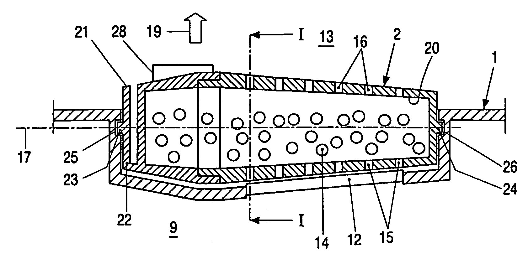
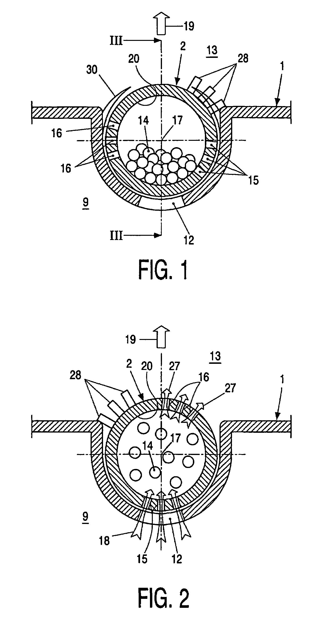
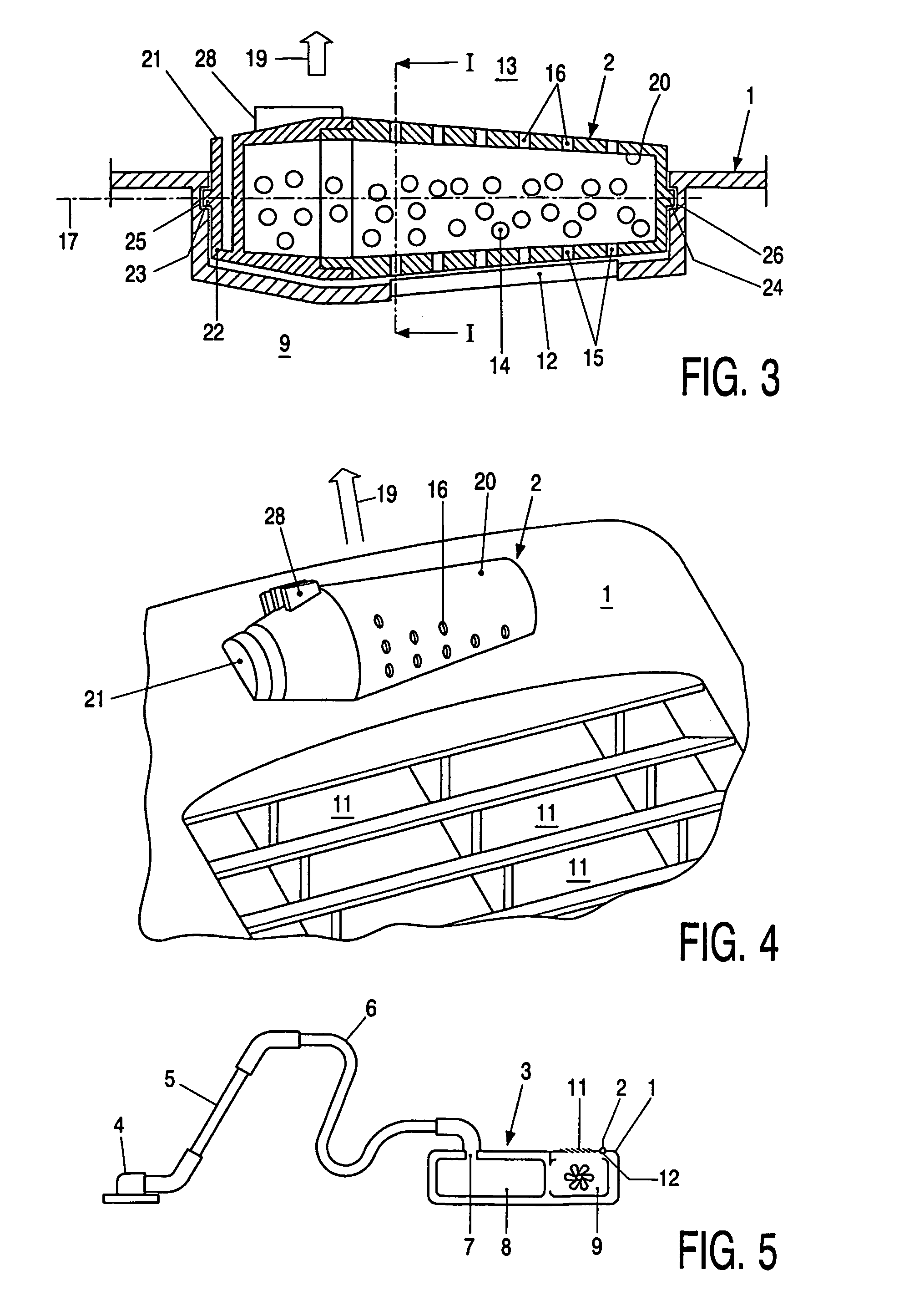
[0022]In FIGS. 1–4, a fragrance dispenser according to the invention is shown which includes a housing portion 1 and a fragrance-carrying cartridge 2 removably mounted to the housing portion 1. A possible location of the housing portion 1 and of the cartridge 2 according to the present example on a vacuum cleaner 3 is shown in FIG. 5. This vacuum cleaner 3 has a suction nozzle 4 connected to a tube 5. The tube 5 is connected to a hose 6. The hose 6 is connected to an inlet passage 7 in a housing of a sledge type vacuum cleaner, which passage 7 leads to the internals of a dust bag 8. An air discharge duct 9 extends from the dust bag 8 through a ventilator unit 10 and air discharge passages 11, 12 to the environment of the vacuum cleaner 3. One of these passages 12 is part of the fragrance dispenser portion of the vacuum cleaner 3 and interconnects an upstream side (in this example formed by the duct 9) of the housing portion 1 and a downstream side 13 (in this example formed by the e...


PUM


Abstract

An improved fragrance dispenser, domestic appliance, such as a vacuum cleaner, including such a fragrance dispenser, and cartridge for such a fragrance dispenser is provided in which the dispenser includes a housing portion through which an air discharge passage interconnecting an upstream side of the housing portion and a downstream side of the housing portion extends, and a cartridge carrying a fragrant substance and having vents for allowing air to pass for entraining fragrance from said cartridge, wherein the cartridge is removably mounted and rotatably adjustable about an axis of rotation between at least a first position and a second position, at least a portion of at least one of the vents being obstructed by a housing portion if the cartridge is in the first position and being open if the cartridge is in the second position. The cartridge is removable in a direction transverse to the axis of rotation, and the dispenser includes means adapted for engaging and releasing the housing portion in a direction transverse to the axis of rotation. The cartridge contains a granular fragrance carrier substrate.

Description

BACKGROUND OF THE INVENTION[0001]The invention relates to a fragrance dispenser comprising a housing portion through which an air discharge passage interconnecting an upstream side of said housing portion and a downstream side of said housing portion extends, and a cartridge carrying a fragrant substance and having vents for allowing air to pass for entraining fragrance from said cartridge, wherein the cartridge is removably mounted and rotatably adjustable about an axis of rotation between at least a first position and a second position, at least a portion of at least one of said vents being obstructed by said housing portion if said cartridge is in said first position and being open if said cartridge is in said second position.[0002]The invention further relates to a domestic appliance, such as a vacuum cleaner, including a fragrance dispenser according to the invention.[0003]The invention also relates to a fragrance dispensing cartridge carrying a fragrant substance and having ve...

Claims


Application Information

Patent Timeline
IPC IPC(8): A61L9/04A47L7/00A47L7/04A61L9/12
CPCA47L7/04A61L9/122A61L9/12A61L9/04A47L7/00
Inventor KUIPER, BERNARDUS LUBBERTUS
Owner KONINKLIJKE PHILIPS ELECTRONICS NV
Learn More